


Related
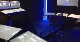
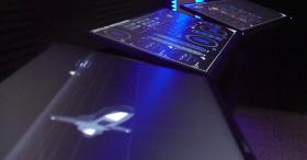
The Vessel Command, Control and Management System (VC2MS) is intended to facilitate intuitive access to relevant system information for rapid diagnosis and control input.
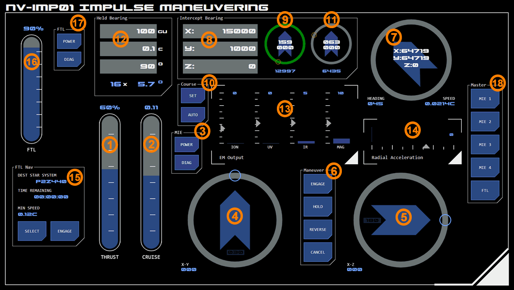 This is a single panel console which controls the vessel’s main impulse engines and monitors the vessel’s position, speed and heading for sublight maneuvering purposes and FTL drive.
1. Thrust Controls
This linear slider controls the thrust output of the main engines, which determines the vessel’s acceleration.
The control measures thrust as a percentage of the engine’s maximum output.
Reverse Thrust
To slow or stop the vessel, reverse thrust must be applied. This diverts engine output through forward-firing outlets, a process which reduces engine efficiency by approximately 25%.
Reverse thrust is applied by tapping the REVERSE button in the maneuvering controls. Whatever thrust level is currently selected on the thrust slider will be applied in reverse.
Thrust will automatically be cut when the vessel reaches “all stop” (no independent momentum). Selecting the HOLD button while reverse thrust is applied will override the all stop default and the vessel will continue to accelerate in reverse until thrust is cut.
The vessel’s bearing cannot be changed while under reverse thrust (see below).
2. Cruise Control
With thrust applied, the vessel will continue to accelerate until thrust is cut or relativistic drag prevents further acceleration. The cruise slider allows the operator to pre-select a target cruise speed, represented as a fraction of lightspeed C. When the target speed is reached, the system will automatically cut thrust and the vessel’s momentum will maintain its current speed.
Cruise control settings are not applied when the vessel is under reverse thrust.
3. Engine Controls
These buttons call up additional configuration and monitoring interfaces for the main impulse engines.
Power
This button displays the power allocation interface for the main engines as an overlay, allowing the operator to manage power allocation (including auxiliary power) to the main engines.
Diagnostic
This button displays diagnostic information for the main engines as an overlay.
Directional Control
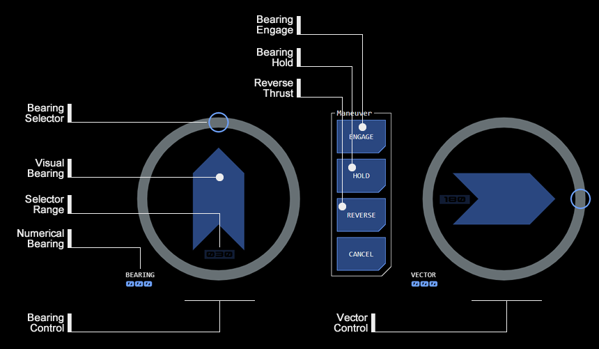
Two radial dials allow the vessel’s direction of travel (heading) to be changed. These dials are reset to zero when the panel starts up.
4. X-Y Bearing Control
The left radial bearing dial allows the user to select an X-Y bearing - the number of degrees by which the vessel’s direction of travel (heading) on the X-Y or horizontal plane is to change.
The dial’s default position is a zero bearing (no change in direction) at the top of the dial.
Sliding the dial anti-clockwise from zero produces a positive bearing, which will adjust the vessel’s heading to port.
Sliding the dial in a clockwise direction from zero produces a negative bearing, which will adjust the vessel’s heading to starboard.
The selected bearing is not applied until the ENGAGE button in the Maneuver Controls is tapped.
The bearing is applied in the next maneuver cycle only, unless the HOLD button is selected.
5. X-Z Bearing Control
The right radial bearing dial allows the user to select an X-Z bearing - the number of degrees by which the vessel’s direction of travel (heading) on the X-Z or vertical plane is to change. This is used to adjust the vessel’s position on the Z-axis (the “vertical” axis relative to the current star system’s orbital plane).
The dial’s default position is a zero bearing (no change in pitch) at the right of the dial.
Sliding the dial anti-clockwise from zero produces a positive bearing, which will adjust the vessel’s pitch upwards.
Sliding the dial in a clockwise direction from zero produces a negative bearing, which will adjust the vessel’s pitch downwards.
The selected bearing is not applied until the ENGAGE button in the Maneuver Controls is tapped.
The bearing is applied in the next maneuver cycle only, unless the HOLD button is selected. At the end of the cycle, the vessel’s pitch is automatically returned to zero (aligned to orbital plane).
Vertical Lock
By default the vertical bearing control is locked to prevent accidental engagement. LOCK status is indicated by the range selector indicator having a (darkened) ALERT state.
When opened from the X-Z radial, the selection range interface (see below) contains an additional LOCK button to toggle the vertical lock on (SELECT state) and off (READY state).
Selection Range
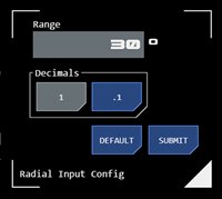
Both bearing and vector controls have a variable selection range, which can be used to increase or decrease the granularity of selections. The current range (in degrees) is indicated by the selection range indicator at the base of the orientation guide. Tapping the indicator opens the selection range interface.
Gimbal Limits
Changing the vessel’s heading or pitch is achieved by adjusting the direction of engine output, a process referred to as “gimballing” the engines. There is a limit to how far the engines can divert output, which limits the size of a bearing or vector change.
The greater the vessel’s speed, the less engine output must be diverted to achieve the same change in heading or pitch. This means that at higher speeds, greater bearings or vectors can be successfully applied.
The numerical bearing indicator on the bearing control dial will change to an ALERT state whenever a bearing selection exceeds gimbal limits at the vessel's current speed.
Reverse Thrust
The reverse thrust diverter system bypasses the engine gimballing system, which means bearing or vector changes cannot be applied while the vessel is under reverse thrust.
6. Maneuver Controls
These buttons are used to manage or apply settings made with speed, thrust or direction sliders.
Engage
Pressing this button will apply whatever settings are current on both the directional radial sliders (bearing and vector). If only a bearing needs to be applied, then the vector slider should be set to zero (and vice versa).
The button acknowledges the ENGAGE command by flashing alert status.
Alarm Codes
If the bearing or vector cannot be applied for any reason, the button will flash alarm status along with an alarm code:
Gimbal: The requested maneuver is outside the main engine gimbal limits.
Reverse: The requested maneuver cannot be completed as reverse thrust is being applied.
No Speed: The vessel currently does not have enough speed (steerage) to complete the maneuver.
Error: This indicates a non-classified system error.
Hold
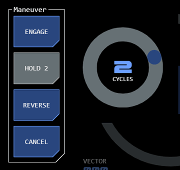
This button allows directional or thrust settings to be “held” across multiple maneuvering cycles.
The button toggles between active and inactive modes. While in active mode, any bearing or vector selection will be applied to every maneuvering cycle until the selected number of cycles has been completed or button is toggled to inactive mode.
A radial slider will be displayed when the button enters active mode. Use this to select the number of cycles required (zero cycles means hold mode will be applied until the button is toggled to inactive mode). The slider will disappear shortly after a selection is made (or if another maneuver control button is tapped), and the active hold button will update to display the selected number of cycles.
To hide the radial slider without making a change, tap the slider's CYCLES label.
When reverse thrust is applied, the HOLD button’s active mode will continue to apply reverse thrust beyond all stop so that the vessel moves backwards.
Reverse
This button applies reverse thrust divertors to slow the vessel.
The button toggles between active and inactive modes.
Cancel
This button cancels a recently applied maneuver.
7. Position Radial
This navigation radial provides information about the vessel’s current grid position, heading and speed.
More on Navigation Radial module
Bearing Display
8. Intercept Bearing
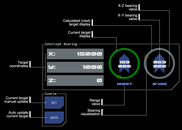
This module allows the bearing, vector and distance to a target grid location to be calculated.
9. Current Target Bearing
This displays data for the current navigational target.
10. Update Current Target Bearing
The SET button manually updates the current target bearing display with the coordinates in the IBC.
When the course AUTO button is active, the current target bearing will update with the coordinates currently in the IBC when the ENGAGE button is tapped. If a simple heading correction is intended, the AUTO button should be toggled inactive to avoid the bearing displays being reset.
11. Calculated Bearing
This displays data for the coordinates currently in the IBC, relative to the current target bearing's co-ordinates and the vessel's current heading. This effectively provides the bearing required for the next maneuver.
12. Held Bearing
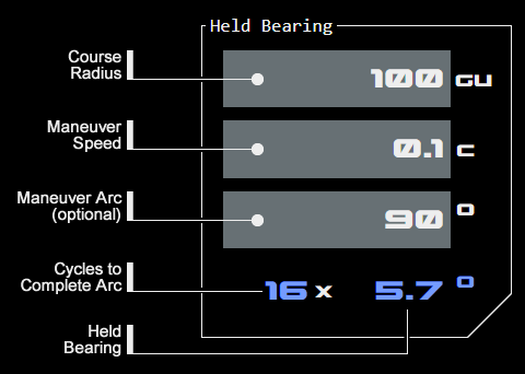
This module allows the correct held bearing for circumnavigation along a desired radius and a given speed. A desired arc can also be input to calculate the number of maneuvering cycles required to complete that arc.
Monitoring
The console includes monitoring of thrust and maneuvering related datapoints.
13. EM Output
This linear monitor displays the EM being output by the main engines, across the relevant EM bands.
Maintaining EM output below detectable thresholds is an important aspect of maneuvering management.
14. Radial Acceleration
This linear monitor displays the radial acceleration forces acting on the vessel. Speed, acceleration and the size of bearing changes all impact how much stress a maneuver places on the vessel’s spaceframe. A maneuver with radial acceleration that is too high may cause damage to the vessel.
FTL Controls
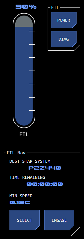 Faster-Than-Light (FTL) flight mode can be engaged and controlled from this section of the console.
While FTL flight mode is considered different to impulse flight mode, there is a close connection between the Base Inertial Velocity (BIV) - which is the vessel's current impulse speed at the time FTL drive is engaged - and impulse flight mode (which delivers the BIV). Because FTL flight mode is highly automated its relatively small control interface footprint allows it to be incorporated on the Impulse Maneuvering console.
15. FTL Drive Module
This module allows the selection of a destination star system. All other navigation and maneuvering functions required to reach the destination are automated.
If the destination star system is displayed in alert state (gold) then the current selection is invalid (usually because the destination selected is the current star system).
Once a star system is selected, the FTL drive can be engaged, provided that correct power levels are set for the FTL drive (see above).
When the FTL drive is engaged all impulse maneuvering controls will be disabled (greyed out) as it is not possible to maneuver while in FTL flight mode.
Alarm Codes
The following alarm codes may be displayed when operating the FTL drive module:
Check Dest: Indicates that the selected destination star system is invalid (or that the current star system has been or remains selected)
Drive Fail: Indicates that the FTL drive has disengaged unexpectedly
In Flight: Indicates a selection that is invalid while the FTL drive is engaged
Speed: Indicates that the vessel has insufficient Base Inertial Velocity (current impulse speed) for the FTL drive to operate at currently selected power levels.
16. FTL Drive Power
This linear slider controls the amount of power allocated to the FTL drive.
The higher the vessel's Base Inertial Velocity (current impulse speed) the less power is required by the FTL drive. The minimum BIV necessary at the current power level is displayed in the FTL drive module (see below) under MIN SPEED.
17. FTL Power and Diagnostics
This accesses standard PDN and diagnostic interfaces for the FTL drive.
18. Master Monitors
Master monitors for the four impulse engine modules display current engine status.
FTL drive status is also displayed.