A draft deck guide including deck plans for each of Endeavour's seven decks has been posted for review and discussion. This is just an initial draft - nothing is close to being finalised yet. The layout is a compromise between crew spaces, machinery/equipment spaces, the location of exterior equipment and the ship's survivability.
The ship's interior is divided into three areas, with the core primary spaces - the "citadel" - the most heavily protected and housing the most critical systems.
Highlights include the (perhaps surprising) amount of space proposed for crew accommodation - each crew member gets their own cabin (even if some have to share a bathroom with another crewmate). This reflects the long, hazardous missions Endeavour is expected to undertake with a mixed military/civilian crew.
The deck guide can be found here, including PDF versions which are easier for zooming into detail. Comment below with your thoughts and suggestions!
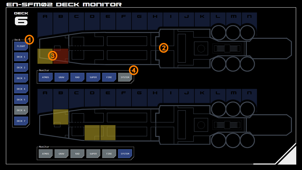
This panel displays deck-specific system and environmental indications, providing more detailed information about an indication displayed on the Master Systems panel.
It shows a schematic plan of the selected deck over which are overlaid alert or alarm conditions for each section. Tapping a section opens an overlay with additional detail.
The panel also incorporates control and command interfaces for damage control, fire fighting and evacuation management.
1. Deck Selection
The deck which is to be monitored is selected from these buttons.
2. Deck Monitor
Two instances of the deck plan are displayed so that different datapoints can be focused using filters (see below). By default the top monitor displays indications from PDN nodes and systems, while the bottom monitor displays environmental indications.
Deck sections are indicated along the top of the monitor, split between port and starboard sections.
Any section can be tapped for more information. If system monitoring is active on the tapped monitor the system details overlay for that section will display by default, otherwise the environmental details overlay will display by default.
3. Status Indications
If a monitored datapoint within a section has an alert or alarm status it is indicated as a semi-transparent overly in that section.
Alert indications are gold.
Alarm indications are red.
4. Datapoint Monitor Selection
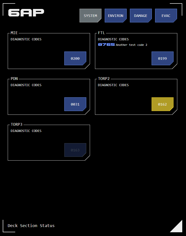
Above: Section system status and diagnostic overlay
Datapoints can be filtered on each deck monitor instance. Tapping a datapoint toggles it between monitored (selected (grey) state) or non-monitored (ready (blue) state).
Section Detail Overlay
Tapping a section (highlighted or not) opens an overlay with key system/PDN or environmental data.
There are two data overlays which can be toggled suing the buttons at the top of the overlay.
Systems
The systems overlay includes PDN nodes and systems, based on the physical location of the node or system on the deck.
Systems may cover multiple sections.
Tapping the system/node number button opens the PDN control interface for that node/system.
Environmental
The environmental overlay includes a number of datapoints:
Atmospheric (Atmos)
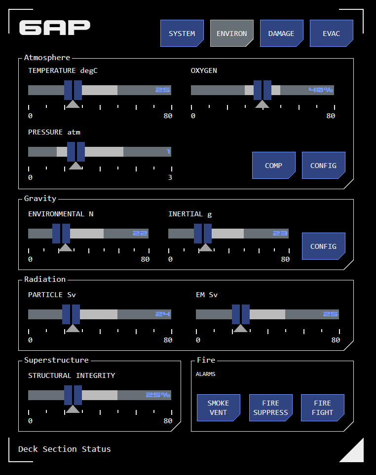
Above: Section environmental data overlay
This datapoint monitors a number of atmospheric parameters in the section:
Temperature: The atmospheric (perceived) temperature, measured in degrees celsius.
Oxygen: Measures the oxygen content as a percentage of atmospheric gases.
Gravity (Grav)
This datapoint monitors artificial gravity and associated inertial dampening within a section.
Environmental: Gravity strength as it effects normal habitation, measured in Newtowns (N).
Inertial: Measures the uncompensated effects of vessel movement over and above nominal. Normally the artificial gravity system is carefully manipulated to compensate for vessel movement, a process referred to as inertial dampening. This prevents crew being thrown around inside the ship as it changes speed or direction. Where crew experience the inertial force of vessel movement (due to a fault or overload of the inertial dampening system) this is measured as g-force (units of standard gravity).
Radiation (Rad)
This datapoint measures radiation detectable within a section.
Particulate: This measures particle-based radiation such as alpha particles (from atomic nuclei) and beta particles (electrons) in dose-equivalent sievert (Sv) units.
EM: This measures high-frequency EM radiation such as X-rays and gamma rays, which can be harmful to humans. This radiation is also measured in sieverts.
Vessel Superstructure (Super)
This datapoint measures the structural integrity of the sections superstructure as a percentage of design rating.
This datapoint also includes an alarm which indicates where the external superstructure (the hull) has breached, exposing the interior of the ship to space.
Fire
This datapoint indicates whether smoke or fire has been detected in the section. Detections are shown as simple alarms.
Buttons also indicate whether automated smoke venting and/or fire suppression systems have been activated, and provide manual overrides of those systems.
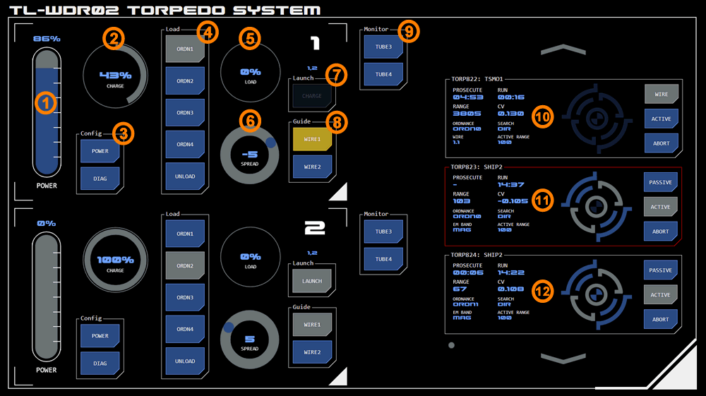
This panel allows torpedoes to be loaded into firing tubes, launched and tracked until prosecution. It includes two modules: torpedo load and torpedo flight status.
Torpedo Load
The status of two firing tubes can be displayed on the panel at once. Additional tubes are selectable from the monitor buttons (9) at the right of the tube status modules.
Torpedo Tube Charging
The firing tube capacitors must be charged before the torpedo can be fired. The amount of power to allocate to charging can be controlled by the linear slider (1). The amount of charge is displayed in a radial monitor (2). Due to the multi-stage design on the railgun launchers used in the tubes torpedoes cannot be fired before full charge is complete.
To discharge the tube, ensure it is unloaded. Thelaunchbutton (7) will display DISCHARGE and tapping it will discharge the tube.
Ordnance Selection
The type of ordnance to be loaded can be selected (4). There are four types available.
A radial monitor displays progress loading the torpedo (5). The torpedo cannot be fired until loading is complete, at which point the radial monitor returns to zero and the button for the selected ordnance displays active status.
Once loaded, a torpedo can be configured with search parameters from the firing solutions panel.
An already loaded torpedo can be unloaded if needed by tapping the UNLOAD button.
Armoury Status
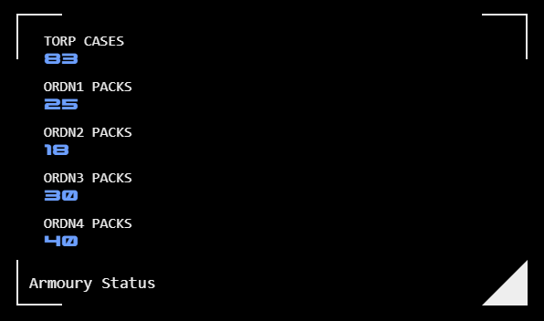
The number of torpedo casings and ordnance packs can be checked by tapping the triangular icons at the bottom-right of either of the tube load modules' frame. An overlay dialogue (right) is displayed and can be dismissed by tapping it's triangular frame icon.
Ordnance is counted as removed from the armoury when loaded. It is added back if the tube is unloaded.
Multiple Launch Configuration
A spread of torpedoes (simultaneous firing of multiple torpedoes) can be configured.
A tube is added to the spread by selecting a spread angle value using the radial slider (6). The torpedo's launch will be offset by this number of degrees. If a zero degree value is required, tap the spread label in the centre of the radial slider. Tapping the label again removes the tube from the spread.
Specifying a non-zero launch angle is only effective when no guidance has been configured for the torpedo, as otherwise the guidance will quickly correct the torpedo's heading.
The tubes included in the spread are indicated immediately above the launch button (9) of every tube included in the spread. The launch of the spread is initiated by the launch button of any of the included tubes.
Launch
The LAUNCH button (9) displays a number of states depending on the status of the tube:
If the tube has been both loaded and is fully charged, the button displays active status and LAUNCH.
If the tube has not been loaded but has been charged, the button displays available status and DISCHARGE.
When the tube has not been charged, the button displays unavailable status and CHARGE.
When the button is active and displays LAUNCH, tapping it will launch the torpedo (and any other torpedoes included in a spread)
Wire Guidance
Two wire guidance transceivers are available and are assigned to a torpedo prior to launch (8).
Once assigned, the transceiver's button remains active until launch, but can be unassigned by tapping the button again.
After launch the button changes to alert status (indicating the transceiver is in use). The transceiver can be released at any time by tapping its button and confirming release. The transceiver will automatically be released when it loses line-of-sight to the torpedo.
Torpedo Flight Status Module
A scrolling list module displays details for all torpedoes in flight. If prosecution is likely to be unsuccessful base don current data (if CV is below zero, for example) then the border will display alarm status (11).
Data Display
Data displayed for each torpedo includes:
Run: This indicates how much time has elapsed since launch
Range: The range of the target (from the torpedo)
Ordnance: The torpedo's ordnance type
Search:The torpedo's configured passive search mode. Where a radial or alternating pattern is configured, this will include bearing and scope.
Some of the datapoints displayed vary depending on the torpedo's flight mode:
Wire Mode (10)
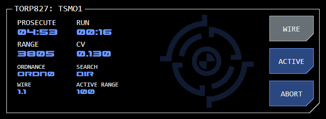
When wire guidance is active (TORP827 example, right), the data display shows:
Prosecute: Estimated time to prosecution
CV: Closing velocity
Wire: Which wire guidance transceiver is being used by this torpedo. The first number is the tube, the second (after the decimal place) indicates which of the tube's two transceivers.
Passive or Active Mode (12)
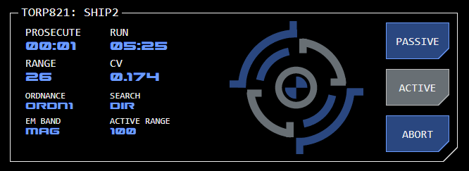
When passive or active mode is engaged (TORP821 example, right), the data display shows the configured EM Band instead of Wire.
No Guidance
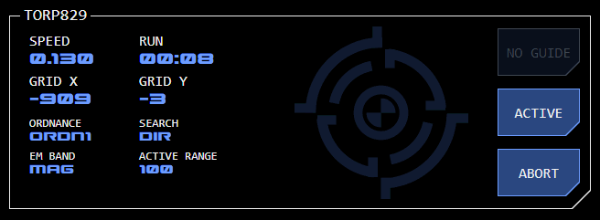
When no guidance is active (TORP829 example, right):
Prosecute is replaced by Speed (indicating the torpedo's estimated speed)
Range is replaced by GridX (the torpedo's estimated X co-ordinate on the TOE grid)
CV is replaced by GridY (the torpedo's estimated Y co-ordinate on the TOE grid)
Range Visualiser
A visualisation (right) indicates at a glance the range to target.
The visualisation has six stages, from top-left moving right:
Stage 1: Outside first range threshold
Stage 2: Range threshold 2000 GUs
Stage 3: Range threshold 1000 GUs
Stage 4: Range threshold 500 GUs
Stage 5: Range threshold 250 GUs
Stage 6: Range threshold 100 GUs
When the system estimates a successful prosecution, the visualiser displays in all red.
Flight Mode Buttons
Three buttons at the right of each torpedo display show the current flight mode and allow the weapons director to manually override the current flight mode, including an option to abort (destroying the torpedo).
From the top:
Wire/Passive
The first button displays active status and WIRE when wire guidance is active. Tapping the button while in this status releases the wire guidance.
When wire guidance is not active, but the torpedo has been configured with passive guidance parameters, the button displays available status and PASSIVE. If no passive guidance has been configured, the button displays unavailable status and NO GUIDE.
Active
The second button manages the torpedo's active (RADAR) guidance system.
At launch the second button displays available status and ACTIVE, indicating active guidance mode is available but has not been engaged.
If the button displays active state, active guidance has been engaged. This can occur automatically if the torpedo reaches the range specified.
Tapping the button at any time will toggle engaging active mode.
Abort
The third button allows the torpedo's flight to be aborted at any time, destroying the torpedo.
If the torpedo has successfully prosecuted, this button will display CLEAR. The torpedo will remain in the list until cleared using this button.
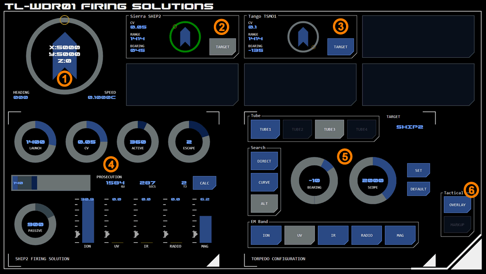
This panel is used for calculating and configuring optimal launch and flight conditions for torpedoes. It displays all available tracked contacts which can be selected as targets for both a firing solution calculator and a torpedo configuration module.
1. Compass
The panel includes a 'compass' module which displays the vessel's current position, speed and heading - providing useful context for targeting purposes.
Target Display
Up to six contacts can be tracked by the vessel at any one time due to the number of narrowband EMDAR arrays available. The contacts currently being tracked are displayed here.
The format of this display is similar to that used by the EMDAR Contacts Board, although the data displayed is slightly different. For example, the contact's closing velocity (CV) is displayed, which is the difference in speed between the contact and the user's vessel (a positive value indicates the contact is slower than the user's vessel).
2. Selected Target
Tapping the target button makes that contact's data available to firing solution calculator and assigns the contact as the target for the torpedo configuration module.
The target button is displayed in active mode and the radial track behind the contact position visualisation is emphasised in green.
Tapping the target button again will deselect the target without setting a new target.
3. Unselected Target
Other contacts available for targeting can be selected by tapping their target button. This replaces any previous target for both the firing solution calculator and torpedo configuration module.
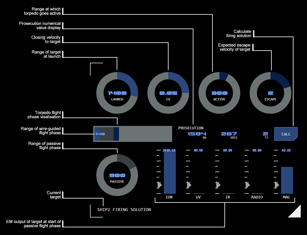
4. Firing Solution Calculator
Above: Torpedo firing solution calculator (click for larger)
The firing solutions calculator allows the operator to explore a number of different range and phasing alternatives for a torpedo’s flight. It allows different conditions for torpedo launch and running time to be assessed for optimal target prosecution.
Each phase of the flight has its own colour code (reflected in the dial and visualisation colours).
Launch (Light Blue)
The launch phase has two dials:
LAUNCH: selects the range to the target when the torpedo is to be launched
CV: Selects the closing velocity (CV) to the target expected at launch.
Wire-Guided Phase
The wire-guided phase is part of the launch phase. Its range isn't set directly, but is calculated by subtracting the active and passive ranges from the launch range. The wire-guided range for a calculated solution is therefore also displayed numerically on the flight phase visualisation.
Active (Dark Blue)
The active (final) phase has two dials:
ACTIVE: Selects the expected range to target when the torpedo goes into active mode.
ESCAPE: Selects the expected opposite thrust the target is expected to be able to apply to escape the torpedo once it goes into active mode (and is detectable).
Passive (Dark Grey)
The passive phase has a single dial, which selects the range the torpedo is expected to fly in passive mode (ie not in either wire-guided or active modes).
TARGET AMBIENT EM: The target's ambient EM at the selected passive range is displayed, so that you can see whether there is sufficient EM coming from the target for the torpedo to detect. Any value below the minimum detectable EM (indicated for each band) will trigger alert status for that band.
Calculation Display
Once values have been set, calculation is triggered by tapping the CAL button. The results of a firing solution calculation are displayed horizontally to the left of the CALC button.
If any required values are not set, the button will flash alarm status and display an error message indicating which value is missing.
If the set values do not result in a successful prosecution the button will flash alarm status and display a RANGE error message.
Range Visualisation
The range of each flight phase is displayed on a horizontal bar graph visualisation. The light grey background indicates the maximum range (by default 5000GUs).
The range of the wire-guided phase is also displayed numerically at the far left (as this range is not set directly and so is not otherwise displayed anywhere else).
Prosecution Results
Numerical results for prosecution are displayed. The calculator uses the vessel's current speed to assist in calculating these results.
From left to right the results are:
RANGE: The expected range of the torpedo's flight before successful prosecution (measured in GUs).
ELAPSED: The expected time elapsed from launch to successful prosecution (measured in seconds).
DAMAGE: The amount of kinetic energy expected at the time the torpedo hits the target (measured in terajoules).
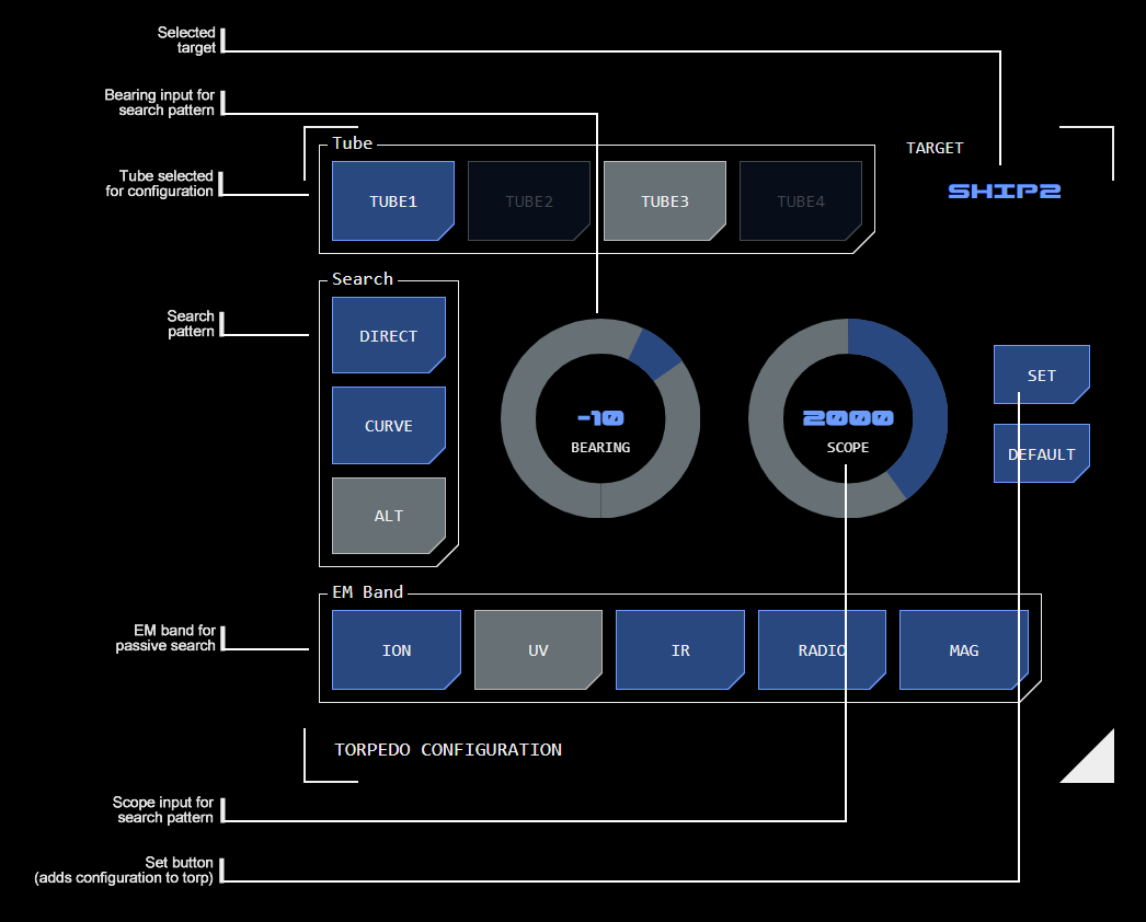
5. Torpedo Configuration
Above: Torpedo configuration module (click for larger)
The torpedo configuration module allows flight search parameters to be added to a loaded torpedo.
Tube Selection
Select the tube that is to be configured. All torpedoes loaded into the tube will receive that configuration. This allows each tube to be assigned specific role within a complex tactical engagement.
The calculator's settings do not change when a new tube is selected. This makes it easier to close tube configurations across tubes. To see the selected tube's configuration, use the CHECK button (see below).
Target
The currently selected target is displayed here. The target is selected from the target board (see above).
Wild Launch
If no target is selected, the torpedo will be fired "wild". Passive search settings will be applied to the first EMDAR data detected (although this will be overridden by the torpedo's IFF system if required).
When setting the configuration without a target, the target display will flash alert mode to prompt the user to confirm they intended this, although the torpedo configuration will still be set.
Search Pattern
The search buttons select the required search pattern for the passive flight phase. The torpedo's EMDAR system covers an arc +/-45° ahead.
Selection radials will display appropriate to the search pattern selected.
Active
This button allows the range from target that automatically triggers the torpedo's active guidance system. Default is 100 GUs.
Where a passive search pattern has been selected (see below) tapping this button will cancel that search pattern and configure the torpedo with a linear course while in passive mode.
Radial
A radial search pattern is defined by the bearing and scope settings. The torpedo will adjust its course so that the bearing (to a maximum of 90°) is completed over the distance (in GUs) set as the scope. It will then resume a linear course.
This search pattern is useful for following a target's course if it is traveling on a course perpendicular to the vessel.
Alt
An alternating (ALT) search pattern (or zig-zag) alters the torpedo's original heading by the bearing selected (to a maximum of 45°), alternating between positive and negative bearings each time the scope time (in seconds) is reached.
This search pattern increases the area of space the torpedo can cover with its EMDAR system.
EM Band
This selects the EM band the torpedo's EMDAR system should use. Torpedo-mounted EMDAR is not as powerful as the vessel's EMDAR system and can only process data from a single band.
Set Button
This button applies the selected configuration to the selected torpedo.
If required parameters are not set, the button will display alarm mode and display an error message indicating the missing parameter.
Check Button
This button displays the current configuration for the selected tube. For display purposes it temporarily replaces existing control settings but these do not become effective until the SET button is tapped.
While the check is active, the target will be displayed with alert status to indicate the check configuration (not the current control status) is being displayed. Changing the target on the target display will not be reflected in the configuration module while the check is active.
The check is cleared when any other button in the configuration module is tapped (tapping the check button does not toggle the check off). To simply clear the check without making any configuration changes, tap the currently selected tube.
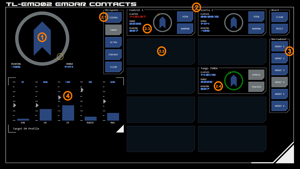
This panel works in conjunction with TL-EMD01. It is dominated by the Contact Board module (in active mode), which allows users to add and manage EMDAR contacts.
1. Contact Orientation
This Navigation Radial instance provides bearing and range data on either the selected contact, or the selected target on the waterfall display (TL-EMD01).
The colour of the circular track changes to indicate which is currently being displayed:
Grey: indicates that range and bearing to the selected waterfall display target is being displayed.
Purple: indicates the range and bearing to the selected contact (from the contact board) is being displayed.
2. Contact Board
This is an active mode instance of the Contact Board module. More information on the operation of this module can be found here.
This array of buttons is used to select a designation for a new contact, or a contact being updated.
2.2 Contact Display (empty)
Up to ten contacts can be managed on the board at any one time, indicated by these areas. This is an example of an empty contact - tapping it will create a new contact with the currently displayed range/bearing and designation.
2.3 Contact Display (contact)
This is an example of an active contact.
2.4 Contact Display (tracked)
When a contact is being tracked by an EMDAR narrowband array, the visual range/bearing display's circular track will display as green instead of grey.
3. Narrowband Arrays
Up to six narrowband EMDAR arrays are available to track contacts. Unlike broadband, narrowband arrays are able to track a contact as it changes position in space. This button array is used to manage the assignment of contacts to narrowband arrays.
4. Target EM Profile
This Linear Monitor instance will display the current EM output of the tracked contact currently being viewed. This data can assist with the identification of a tracked contact. Contacts not currently being tracked by a narrowband array will not generate any data for display in this module.
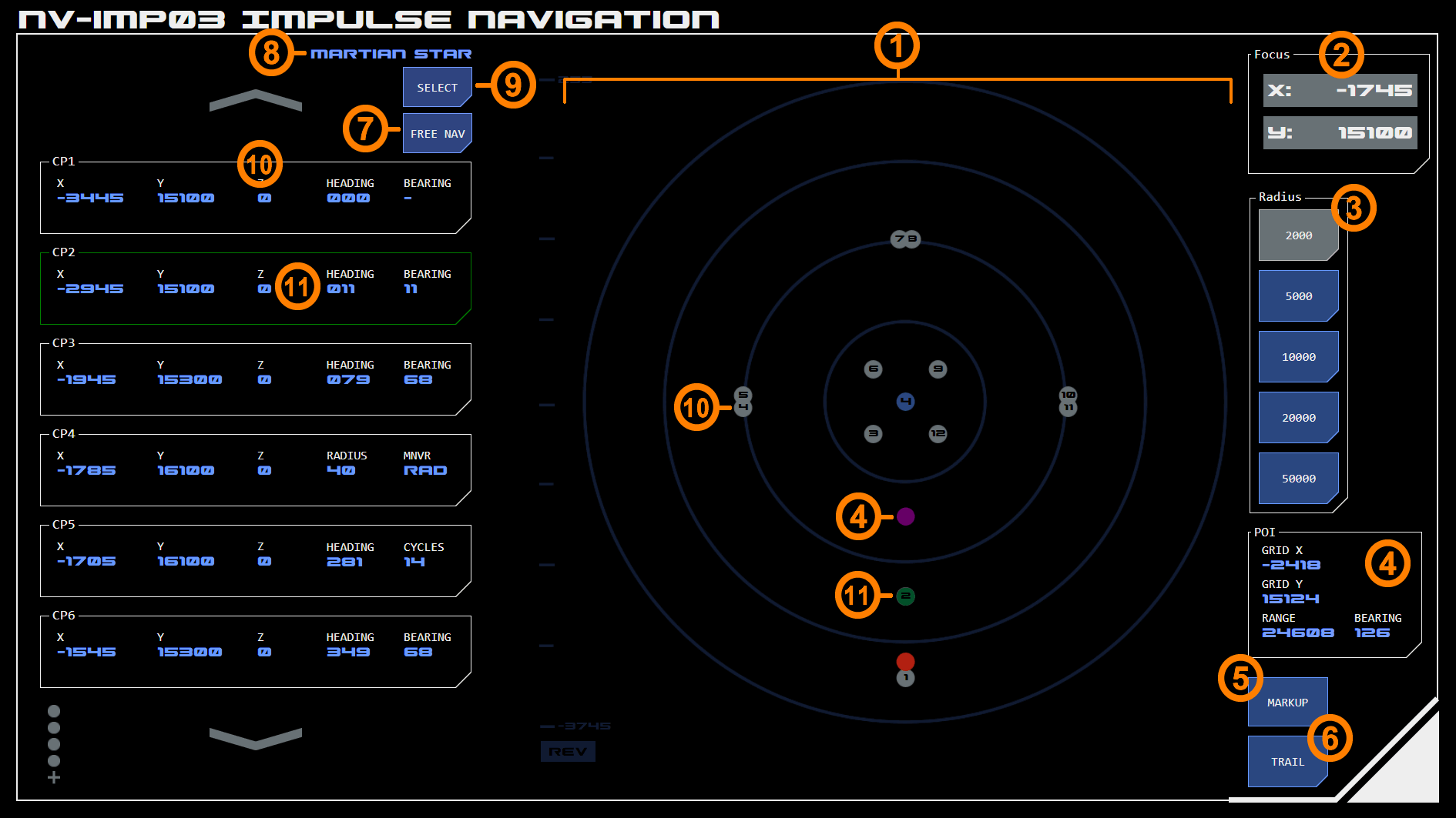
Above: Impulse navigation console in pre-plot mode
The Impulse Navigation panel assists with navigation against pre-plotted courses during impulse operations.
The panel consists of a scrollable list of course points and a 2D impulse map displaying the location of the course points, Astronomical Objects (AOs) and the vessel.
The console has two modes.
Pre-plot mode allows the user to select from a list of courses plotted by a navigator, typically standard search patterns or a course with specific mission requirements.
Free-nav mode allows the user to select Points of Interest (POI's) from the impulse map and save these as course points.
Common Features
The console has a number of features which are common to both modes.
1. Impulse Map
The impulse map displays course points as silver dots, with the point’s order number displayed in the centre. The currently highlighted course point is displayed as a green dot.
Where multiple course points overlap, the earliest course point will be displayed until the vessel navigates beyond the following course point, after which the later course point will be displayed.
Stars are displayed as yellow dots with their designation listed below. Other AO’s are displayed as blue dots with their system number displayed in the centre.
Other impulse map features such as the ability to set the map’s focus co-ordinates and radius (scale) work as normal. Focus and radius may be updated automatically when a new course is selected, although this can then be overridden by the user.
Markup and course trail options can be activated at the bottom right of the map ((7).
2. Focus
The center of the impulse map is it's focus. The co-ordinates of the map focus can be set here.
Alternatively, tapping the currently active radius button will re-focus the map on the vessel.
3. Map Radius
The impulse map's radius (in GUs) can be selected from one of five options.
Courses Relative to Map
Courses are relative to the panel's current focus and map radius. Changing either will shift all course points to match the change.
4. Point of Interest (POI)
Tapping any point on the impulse map will activate a purple dot (which represents the POI) and display the POI's co-ordinates in an interface at the bottom right of the panel. Bearing and range of the POI from the vessel are also displayed.
5. Markup
This activates the markup capability of the impulse map, which allows users to draw lines on the map representing possible courses, areas of concern, etc. See the impulse mapping module page for more detail on this feature.
Tapping this toggles between showing a navigation trail behind the vessel, which indicates previous navigation activity.
7. Mode Toggle
This button toggles between pre-plot and free-nav modes (see below).
Pre-Plot Mode
This section refers to the pre-plot example above.
8. Current Course
This indicates which pre-plotted course is currently being displayed (in this example the Martian Star course for training exercises).
9. Course Select
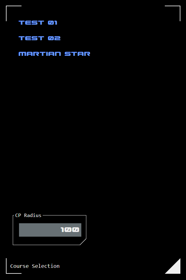
Above: Course selection interface
Tap this button to select a new course from a list of available courses.
When a new course is selected it may include default radius and focus information. If so, the impulse map will automatically update with this new configuration.
10. Course Point List
This scrollable list displays the course points included with the selected course. An example course point is shown.
Each course point includes the grid co-ordinates, the heading required from that course point, and the bearing required to achieve that heading. The first course point does not show a bearing as this is dependent on the approach heading.
The displayed bearing is relative to the previous course point and does not update based on the vessel's heading, even when the course point is currently the target (see 11 below).
Maneuver Types
Where appropriate particular maneuver types will be specified for a course point.
Radial Maneuver
A radial maneuver requires a bearing applied over a series of maneuvering cycles that results in a circular course of a particular radius.
A radial maneuver has two course points. The entry course point has a maneuver type of RAD and specifies the radius required for the maneuver (instead of displaying a heading). In the example panel image, CP4 is the entry course point for a radial maneuver.
The exit course point displays the heading required at the end of the maneuver, but displays the number of maneuvering cycles required to reach that heading (instead of displaying a bearing). The number of maneuvering cycles is calculated based on the currently selected cruise speed and the radius specified in the entry course point. The underlying calculation is the same used by the Held Bearing Calculator (HBC). In the example panel image, CP5 is the exit course point for a radial maneuver.
11. Current Target Course Point
The specific course point currently being navigating towards is highlighted green (as is the corresponding dot on the map). On loading the panel the first course point is highlighted by default. The highlight can be moved by tapping the desired course point. To remove the highlight, tap the already highlighted course point.
When the vessel navigates to the current course point the highlight automatically moves to the next course point. The sensitivity of this (ie how close the vessel has to get to the course point to trigger the change) is adjustable using the CP Range dialog under the course selection list.
Free-Nav Mode
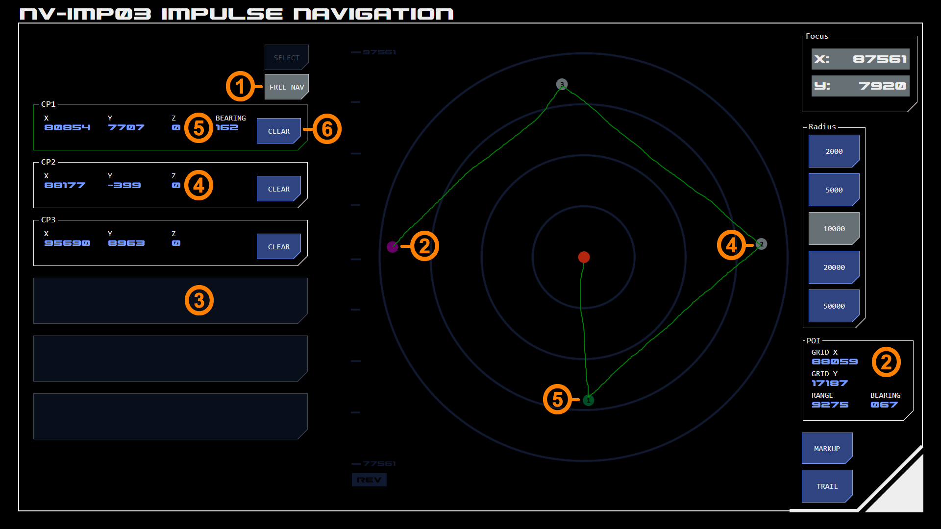
Above: Impulse navigation console in free-nav mode with sample markup shown in green
In this mode users can select their own course points on the impulse map. This is usually done in conjunction with markup - a course is drawn on the map (shown in green on the example) and course points selected where heading changes are required by the drawn course.
1. Mode Toggle
When in free-nav mode the mode toggle button displays selected state.
2. Point of Interest (POI)
The POI is displayed the same way in both nodes, but in free-nav mode the purple dot and POI data display indicate what will be transferred to the course point list.
3. Course Point List Target
Any empty course point list item can be selected to add a course point. When tapped, the list item will be populated with the current POI data and a corresponding course-point will replace the POI dot on the impulse map.
4. Course Point
The course point list displays grid co-ordinates for each course point. Course points are shown on the map as silver dots with their course point number in the centre.
A maximum of six course points can be plotted at any one time.
Course points will always have the number corresponding to their position on the list.
5. Target Course Point
The course point currently being navigated toward (the target course point) can be selected by tapping anywhere in the course point item (except the CLEAR button).
This changes the item's border to green (with the corresponding dot on the impulse map also changing to green).
A target course point will also display the current bearing from the vessel to that course point. This is constantly updated.
Unlike pre-plot mode, the target does not automatically change to the next course point. Users can manually select the next course point by tapping it.
Tapping the current target will disengage it as a target.
6. Clear Course Point
Tapping the CLEAR button removes the course point from the course point list and map.
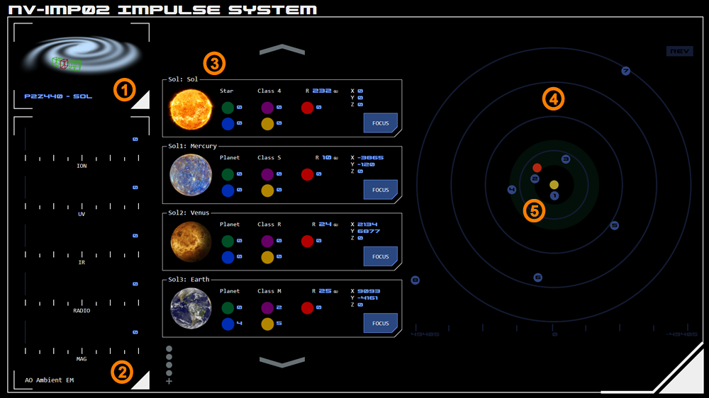
The Impulse System Operations panel provides information on the Astronomical Objects (AOs) in the stellar system the vessel is currently operating in.
1. System Identification
This module identifies the current stellar system, including its reference number, informal designation (if available) and navigation sector.
2. AO Ambient EM
This module displays the ambient EM of the system's Navigable Astronomical Object (NAO) - which is usually the system's star.
The default display can be overridden temporarily by selecting a focus button on the AO list (see below). When a specific focus is selected, the ambient EM of that AO will be displayed instead.
3. AO List
This module displays a scrollable list of the system's major AOs. It provides the AO's reference number, informal designation (if available), type and class along with a visual representation (which is not to scale).
Position Information
The grid position and radius of each AO is provided.
EM Output
The EM output (at source) of each AO is listed using standard color codes to identify the EM band:
Green: Ionising radiation EM band
Red: Infrared EM band
Violet: Ultraviolet EM band
Blue: Radio EM band
Yellow: Magnetic
Focus
The FOCUS button will highlight the selected AO on the AO Map (see below) and change the focus of the Ambient EM to the selected AO.
4. AO Map
This module provides a simplified representation of AO positions.
The Y axis is represented horizontally. The X axis is represented vertically.
Colour Codes
The NAO is represented as yellow (and is typically in the centre of the map).
Other AOs are represented as blue, An AO that has been focussed (see above) will be displayed in grey.
The vessel's current position is represented as red.
Scale
The scale of the map is represented at the bottom of the module in Grid Units (GUs).
Map Orientation
By default the X axis is displayed with negative values at the top of the module and positive values at the bottom according to the standard Cartesian model.
Some operators may find it more intuitive to reverse the axes so that the map's orientation matches vessel orientation indicators (such as the "compass").
The current orientation is indicated by a symbol in the top-right of the map, which displays REV when in reverse orientation mode and STD when in standard orientation mode. Tapping the symbol toggles between the modes.
5. Green Zone Indicator
A system's "green" or habitable zone is indicated as a dark green area on the map, to assist targeting of AOs most likely to meet mission or exploration criteria.
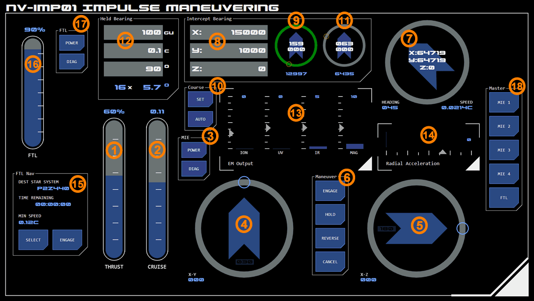
This is a single panel console which controls the vessel’s main impulse engines and monitors the vessel’s position, speed and heading for sublight maneuvering purposes and FTL drive.
1. Thrust Controls
This linear slider controls the thrust output of the main engines, which determines the vessel’s acceleration.
The control measures thrust as a percentage of the engine’s maximum output.
Reverse Thrust
To slow or stop the vessel, reverse thrust must be applied. This diverts engine output through forward-firing outlets, a process which reduces engine efficiency by approximately 25%.
Reverse thrust is applied by tapping the REVERSE button in the maneuvering controls. Whatever thrust level is currently selected on the thrust slider will be applied in reverse.
Thrust will automatically be cut when the vessel reaches “all stop” (no independent momentum). Selecting the HOLD button while reverse thrust is applied will override the all stop default and the vessel will continue to accelerate in reverse until thrust is cut.
The vessel’s bearing cannot be changed while under reverse thrust (see below).
2. Cruise Control
With thrust applied, the vessel will continue to accelerate until thrust is cut or relativistic drag prevents further acceleration. The cruise slider allows the operator to pre-select a target cruise speed, represented as a fraction of lightspeed C. When the target speed is reached, the system will automatically cut thrust and the vessel’s momentum will maintain its current speed.
Cruise control settings are not applied when the vessel is under reverse thrust.
3. Engine Controls
These buttons call up additional configuration and monitoring interfaces for the main impulse engines.
Power
This button displays the power allocation interface for the main engines as an overlay, allowing the operator to manage power allocation (including auxiliary power) to the main engines.
Diagnostic
This button displays diagnostic information for the main engines as an overlay.
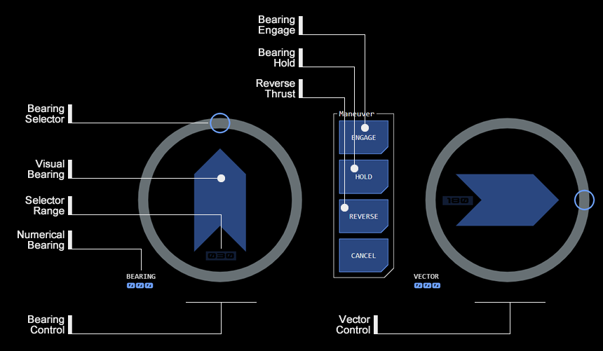
Directional Control
Above: Directional controls (click for larger)
Two radial dials allow the vessel’s direction of travel (heading) to be changed. These dials are reset to zero when the panel starts up.
4. X-Y Bearing Control
The left radial bearing dial allows the user to select an X-Y bearing - the number of degrees by which the vessel’s direction of travel (heading) on the X-Y or horizontal plane is to change.
The dial’s default position is a zero bearing (no change in direction) at the top of the dial.
Sliding the dial anti-clockwise from zero produces a positive bearing, which will adjust the vessel’s heading to port.
Sliding the dial in a clockwise direction from zero produces a negative bearing, which will adjust the vessel’s heading to starboard.
The selected bearing is not applied until the ENGAGE button in the Maneuver Controls is tapped.
The bearing is applied in the next maneuver cycle only, unless the HOLD button is selected.
5. X-Z Bearing Control
The right radial bearing dial allows the user to select an X-Z bearing - the number of degrees by which the vessel’s direction of travel (heading) on the X-Z or vertical plane is to change. This is used to adjust the vessel’s position on the Z-axis (the “vertical” axis relative to the current star system’s orbital plane).
The dial’s default position is a zero bearing (no change in pitch) at the right of the dial.
Sliding the dial anti-clockwise from zero produces a positive bearing, which will adjust the vessel’s pitch upwards.
Sliding the dial in a clockwise direction from zero produces a negative bearing, which will adjust the vessel’s pitch downwards.
The selected bearing is not applied until the ENGAGE button in the Maneuver Controls is tapped.
The bearing is applied in the next maneuver cycle only, unless the HOLD button is selected. At the end of the cycle, the vessel’s pitch is automatically returned to zero (aligned to orbital plane).
Vertical Lock
By default the vertical bearing control is locked to prevent accidental engagement. LOCK status is indicated by the range selector indicator having a (darkened) ALERT state.
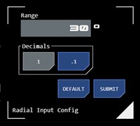
When opened from the X-Z radial, the selection range interface (see below) contains an additional LOCK button to toggle the vertical lock on (SELECT state) and off (READY state).
Selection Range
Above: Radial selection range interface
Both bearing and vector controls have a variable selection range, which can be used to increase or decrease the granularity of selections. The current range (in degrees) is indicated by the selection range indicator at the base of the orientation guide. Tapping the indicator opens the selection range interface.
Gimbal Limits
Changing the vessel’s heading or pitch is achieved by adjusting the direction of engine output, a process referred to as “gimballing” the engines. There is a limit to how far the engines can divert output, which limits the size of a bearing or vector change.
The greater the vessel’s speed, the less engine output must be diverted to achieve the same change in heading or pitch. This means that at higher speeds, greater bearings or vectors can be successfully applied.
The numerical bearing indicator on the bearing control dial will change to an ALERT state whenever a bearing selection exceeds gimbal limits at the vessel's current speed.
Reverse Thrust
The reverse thrust diverter system bypasses the engine gimballing system, which means bearing or vector changes cannot be applied while the vessel is under reverse thrust.
6. Maneuver Controls
These buttons are used to manage or apply settings made with speed, thrust or direction sliders.
Engage
Pressing this button will apply whatever settings are current on both the directional radial sliders (bearing and vector). If only a bearing needs to be applied, then the vector slider should be set to zero (and vice versa).
The button acknowledges the ENGAGE command by flashing alert status.
Alarm Codes
If the bearing or vector cannot be applied for any reason, the button will flash alarm status along with an alarm code:
Gimbal: The requested maneuver is outside the main engine gimbal limits.
Reverse: The requested maneuver cannot be completed as reverse thrust is being applied.
No Speed: The vessel currently does not have enough speed (steerage) to complete the maneuver.
Error: This indicates a non-classified system error.
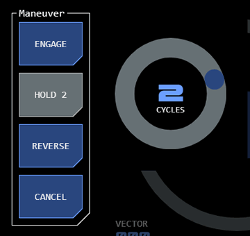
Hold
Above: Hold button in active mode. The radial slider is used to select the number of cycles over which the hold should apply
This button allows directional or thrust settings to be “held” across multiple maneuvering cycles.
The button toggles between active and inactive modes. While in active mode, any bearing or vector selection will be applied to every maneuvering cycle until the selected number of cycles has been completed or button is toggled to inactive mode.
A radial slider will be displayed when the button enters active mode. Use this to select the number of cycles required (zero cycles means hold mode will be applied until the button is toggled to inactive mode). The slider will disappear shortly after a selection is made (or if another maneuver control button is tapped), and the active hold button will update to display the selected number of cycles.
To hide the radial slider without making a change, tap the slider's CYCLES label.
When reverse thrust is applied, the HOLD button’s active mode will continue to apply reverse thrust beyond all stop so that the vessel moves backwards.
Reverse
This button applies reverse thrust divertors to slow the vessel.
The button toggles between active and inactive modes.
Cancel
This button cancels a recently applied maneuver.
7. Position Radial
This navigation radial provides information about the vessel’s current grid position, heading and speed.
More on Navigation Radial module
Bearing Display
8. Intercept Bearing
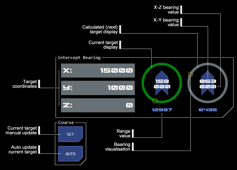
Above: Intercept Bearing Calculator (IBC) (Click for larger)
This module allows the bearing, vector and distance to a target grid location to be calculated.
This displays data for the current navigational target.
10. Update Current Target Bearing
The SET button manually updates the current target bearing display with the coordinates in the IBC.
When the course AUTO button is active, the current target bearing will update with the coordinates currently in the IBC when the ENGAGE button is tapped. If a simple heading correction is intended, the AUTO button should be toggled inactive to avoid the bearing displays being reset.
11. Calculated Bearing
This displays data for the coordinates currently in the IBC, relative to the current target bearing's co-ordinates and the vessel's current heading. This effectively provides the bearing required for the next maneuver.
12. Held Bearing
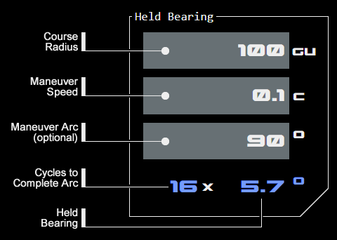
Above: Held Bearing Calculator (HBC) example. (Click for larger)
This module allows the correct held bearing for circumnavigation along a desired radius and a given speed. A desired arc can also be input to calculate the number of maneuvering cycles required to complete that arc.
The console includes monitoring of thrust and maneuvering related datapoints.
13. EM Output
This linear monitor displays the EM being output by the main engines, across the relevant EM bands.
Maintaining EM output below detectable thresholds is an important aspect of maneuvering management.
14. Radial Acceleration
This linear monitor displays the radial acceleration forces acting on the vessel. Speed, acceleration and the size of bearing changes all impact how much stress a maneuver places on the vessel’s spaceframe. A maneuver with radial acceleration that is too high may cause damage to the vessel.
FTL Controls
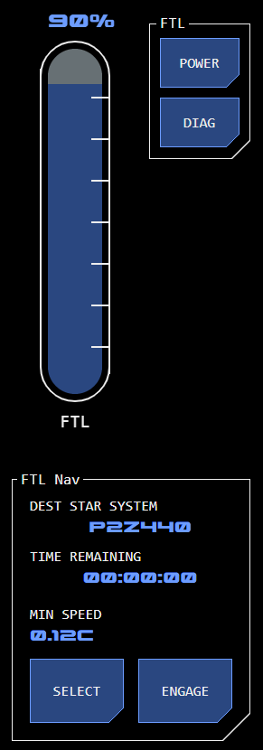
Faster-Than-Light (FTL) flight mode can be engaged and controlled from this section of the console.
While FTL flight mode is considered different to impulse flight mode, there is a close connection between the Base Inertial Velocity (BIV) - which is the vessel's current impulse speed at the time FTL drive is engaged - and impulse flight mode (which delivers the BIV). Because FTL flight mode is highly automated its relatively small control interface footprint allows it to be incorporated on the Impulse Maneuvering console.
This module allows the selection of a destination star system. All other navigation and maneuvering functions required to reach the destination are automated.
If the destination star system is displayed in alert state (gold) then the current selection is invalid (usually because the destination selected is the current star system).
Once a star system is selected, the FTL drive can be engaged, provided that correct power levels are set for the FTL drive (see above).
When the FTL drive is engaged all impulse maneuvering controls will be disabled (greyed out) as it is not possible to maneuver while in FTL flight mode.
Alarm Codes
The following alarm codes may be displayed when operating the FTL drive module:
Check Dest: Indicates that the selected destination star system is invalid (or that the current star system has been or remains selected)
Drive Fail: Indicates that the FTL drive has disengaged unexpectedly
In Flight: Indicates a selection that is invalid while the FTL drive is engaged
Speed: Indicates that the vessel has insufficient Base Inertial Velocity (current impulse speed) for the FTL drive to operate at currently selected power levels.
16. FTL Drive Power
This linear slider controls the amount of power allocated to the FTL drive.
The higher the vessel's Base Inertial Velocity (current impulse speed) the less power is required by the FTL drive. The minimum BIV necessary at the current power level is displayed in the FTL drive module (see below) under MIN SPEED.
17. FTL Power and Diagnostics
This accesses standard PDN and diagnostic interfaces for the FTL drive.
18. Master Monitors
Master monitors for the four impulse engine modules display current engine status.
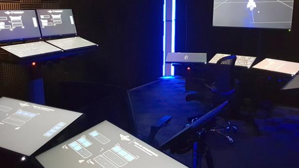
The primary interface to the Vessel Command and Control Management System (VC2MS) are touch screens. These display a predefined group of modular software control inputs and data visualisations – known as a panel - for managing a particular shipboard function. A screen can be configured to display any panel.
Groups of screens are installed to allow multiple functions of a particular ship system to be monitored and managed. For example, the helm has three horizontally-mounted screens which allow for key maneuvering and navigation panels to be available the helm operator. These groups of screens are referred to as consoles.
Physical Configuration
Consoles have two main kinds of mounting configuration.
Deck Mount
A deck mount offers a height-adjustable tabletop surface onto which multiple screens can be mounted in both horizontal or vertical orientations (or a combination). Horizontal orientation provides for more natural control input and allows the operator to see beyond the console to other areas on the deck. Vertical orientation restricts visibility beyond the console but allows for greater screen density.
Deck mounts can be two or three screens wide, depending on space and functional requirements.
Deck mounts can be configured for seated or standing operation.
Bulkhead Mount
A bulkhead mount has screens attached directly to the bulkhead in a vertical orientation. This type of mount is typically used for screens that have a primarily monitoring function.
Software Configuration
The specific panels displayed on a console can be changed depending on operating mode. For example, if the helm operator needs to shift from impulse to RCS maneuvering, the impulse panels can be swapped out for RCS panels.
This also means that operators can customise consoles to their requirements or preference.
Main Consoles
Consoles configured in the training simulator include:
Helm
The helm is the primary navigation console and is a deck mount three screens wide with screens solely in horizontal configuration and typically operated in seated position to allow visibility of the main viewer.
The tactical console is a deck mount two screens wide with screens in both horizontal and vertical configuration, typically operated by one or two operators standing.
The science console is a deck mount three screens wide with screens solely in horizontal configuration by a standing operator to allow visibility over the conn to the main viewer.
The operations console is a deck mount two screens wide with screens in both horizontal and vertical configuration, typically operated by one or two operators standing (an engineer, an operations officer or both).
The Vessel Command, Control and Management System (VC2MS) is intended to facilitate intuitive access to relevant system information for rapid diagnosis and control input.
The system uses touchscreen interfaces to maximise configurability, meaning any system could be controlled from any console on the ship.
Hardware
The VC2MS is accessed physically via groups of touchscreens.
Screen
A screen is an individual touch screen which has its own Standard Compute Unit (SCU).
Each screen can be configured to display a selectable control interface panel (see software below).
Console
A console is a group of panels mounted together. The number of panels reflects the functional requirements of the system being controlled, with a number of standard configurations also reflecting the environmental context of the console’s location. For example, on the bridge the configuration of consoles reflects the need for operators to confer with each other.
Hardware screens display software for the monitoring and control of vessel systems.
Panel
A panel is a pre-configured group of software control inputs and data visualisations displayed on an individual hardware screen (see above) for the management of a particular vessel function.
Panel layouts are modular, reusing functional components to ensure consistent operation, while providing for specialist capability where needed.
The interface aims to communicate critical information clearly for rapid visual assessment. Control interfaces are designed to simplify system operation, supported by automation and integrated AI.
User Interface
A consistent ‘design language’ across all systems assists with accuracy of data assessment and ease of operation.
A wide range of reusable and specialist functional modules are available for interfaces. Even though they may have widely varied functional designs they all adhere to a number of common visual protocols and layout devices.
Visual Protocols
Colour is used across the VC2MS as consistently as possible. There are a number of protocols which describe the appropriate use of colour in different functional contexts.
A number of common visual devices assist with interface layout and usability.
Visualisation Frame
A simple frame consisting of three corner markers and a triangular button is used to present visualisations, which can be in the form of graphs, 3D models, maps, data, etc. The frame may also used around a large group of control and data display modules, especially where configuration functionality associated with the group is needed (see below)
A frame label at the bottom left describes the function of the framed components.
A visualisation can be presented as a core part of a console panel or as a modal overlay.
The triangular button is tapped to access configuration or extended functionality. If the visualisation is a modal overlay, the triangular button closes the overlay.
Functional Group
A functional group includes one or more control and/or data display instances which are related to a particular system function.
The group is contained within a continuous frame with a label describing the group’s function at the top right.
Button Gangs
A group of buttons related to a common function are surrounded by a frame, with a label describing the gang’s function at the top-left. Gangs may be presented vertically or horizontally.
Single Select
Each button within the gang acts independently, each controlling a component or aspect of a common function.
Radio Format
Buttons have interrelated functionality, usually as a range of options for a single function of which only one can apply at a time. Tapping one button deselects the currently active button in favour of the tapped button.
Indicators
Buttons may primarily be used to indicate the current status of related system components (such as master alarm gangs). Tapping the button simply displays additional status information.
Data Display
Data can be displayed in any number of ways depending on the module used.
Basic data display in numerical or word form has a common format.
Datapoints
A datapoint may have a number of visual components.
Data Display
The actual datapoint is displayed in mid-blue using the stylised font.
Datapoint Label
A label describing the datapoint may be displayed above/left or inline before the data. This will be in white using the simple font.
Unit of Measure/Suffix
A Unit of Measure (UOM) or suffix may be displayed inline after or below/right the data.
Direct Data Input
Where a numeric display accepts direct data input via a keypad, this will be indicated by the datapoint displayed in white against a light-grey background. Tapping the datapoint opens the input keypad as an overlay for data entry.
Control Inputs
There are two core control input types.
Buttons
Above: Button examples showing different states
The simplest input is a button, which typically has a Boolean function – the system is either active or inactive.
Buttons may have different selection types.
Toggle
Each tap of the button swaps between two states and remains on that state until tapped again.
Push
Tapping the button initiates the control function and after a short confirmation the button returns to its nominal state.
Hold
Tapping the button initiates the control function and remains engaged until tapped again.
Indicator
The button is used to indicate the status of a system component. Tapping the button simply displays additional status information.
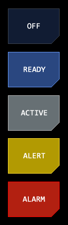
Button Status
The button’s colour and text label may change to indicate the current status of the control function.
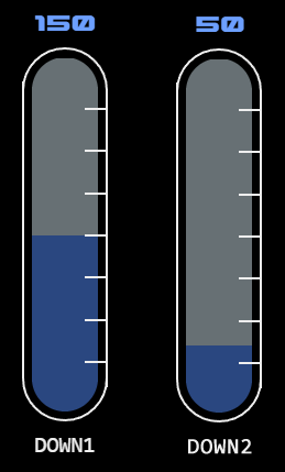
Sliders allow the selection of a value within a range, such as when applying power to a system.
The length of the slider represents the available range, represented by a grey background.
The area between the base of the slider and currently selected value is shown in blue. The current value will also be displayed numerically.
A tap-hold at the top of the blue selected area and sliding will move the top of the selected area in that direction, following the current position of the tap-hold. Lifting off the slider will select the value at that point.
Linear Slider
Linear sliders allow a vertical or horizontal selection along a straight track. These are typically used for power inputs for major systems as they are easier to use accurately.
A graticule overlays the right of the slider showing increments from 20% to 80% of range.
A label at the bottom of the slider describes its function.
Radial Slider
Radial sliders allow selection around a circular track. They are used to save space or where the form factor is otherwise more suitable (for example where the position of the selected point has particular visual significance).
Radial sliders should not be confused with navigation radials which have similar functionality but have visual/functional differences and are specific to navigation.
Indicator Mode
Radial sliders may be presented as indicators only, with no input function. This is typically used for progress display.
An additional thin line around the main track shows the radial in in indicator mode. Typically, only the selected (blue) track is shown in this mode, not the grey (range/background) track.
Jog Mode
A round blue indicator is presented in place of the active/selection range. Tap-hold and sliding the indicator changes the control input value in the applicable direction.
In this mode the control input value is not limited by the slider’s range – multiple circuits of the track are possible to keep increasing/decreasing the value.



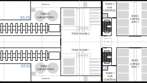 A draft deck guide including deck plans for each of Endeavour's seven decks has been posted for review and discussion. This is just an initial draft - nothing is close to being finalised yet. The layout is a compromise between crew spaces, machinery/equipment spaces, the location of exterior equipment and the ship's survivability.