June 2025

Impulse Maneuvering

Impulse maneuvering uses the main engines to control acceleration, speed and heading.

Speed

The vessel’s speed is measured in fractions of the speed of light (the abbreviation for which is C). The vessel’s maximum rated speed is 0.2C (one-fifth the speed of light, or approximately 60,000 kilometres per second).

A dead-reckoning system estimates the vessel’s speed based on thrust and range of gyroscopic and other sensors. This is part of the same system that estimates the vessel’s position on the navigation grid. It can be impacted by a range of environmental systems and so does not deliver pin-point accuracy but is considered accurate enough for impulse maneuvering, within +/- 3000Km.

Speed is therefore referred to in more approximate terms for operational purposes. Fractions of ‘impulse speed’ typically provide enough specificity. Full (maximum) impulse represents the vessel’s maximum subluminal speed. Half impulse represents half the vessel’s maximum speed (0.1C).

Thrust
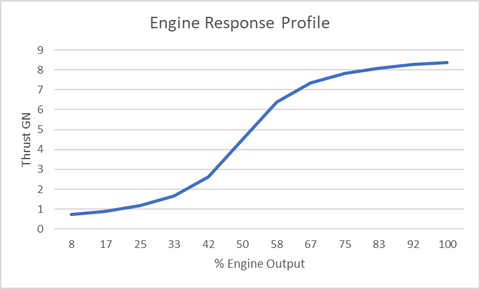
Graph of engine response profile
Above: Impulse engine thrust output profile

The vessel uses Magnetoplasma Impulse Engines (MIE's or impulse engines) to supply thrust for maneuvering. Th helm controls the application of power to the impulse engines, which has a corresponding effect on thrust output.

Impulse engines are extremely energy intensive and efficiency varies over their operating range, with most efficient thrust production experienced mid-range.

Thrust is measured in giganewtons (GN). At nominal efficiency the engines output approximately 4.5GN of thrust, with a maximum rated output of 8.25GN.

Drive Mode

Drive Mode involves the application of thrust to accelerate the vessel to a required speed. Heading changes are typically avoided while in at higher rates of acceleration. Depending on the amount of thrust the main engines output significant detectable EM.

Cruise Mode

Once the vessel has reached the required speed, thrust is reduced and the vessel's momentum maintains velocity. This is referred to as Cruise Mode. Almost no detectable EM is output by the engines in this mode.

Reverse Thrust

If the vessel needs to be slowed or stopped, then reverse thrust must be applied using plasma diverters and forward-facing impulse outlets which counteract the vessel’s forward momentum.

Reverse thrust is applied less efficiently due to the plasma diversion process and the smaller profile of the reverse thrusters.

Acceleration

While thrust is applied the vessel will continue to accelerate, subject to environmental or relativistic factors (see below).

1GN of thrust delivers acceleration of approximately 33Km/sec2 at 0.01C.

Relativistic Drag
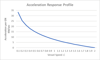
Graph of engine acceleration response profile
Above: Effect of relativistic drag as vessel speed increases

The vessel’s acceleration and maximum speed is limited by relativistic factors. Relativity holds that at the speed of light the vessel’s mass would be infinite (requiring infinite energy to propel it) which is why the space-warping technology of the superluminal engines is required for faster-than-light travel.

This means that as the vessel approaches the speed of light its relative mass increases, a process referred to as relativistic drag. At higher speeds more thrust is therefore required to provide the same amount of acceleration, until maximum thrust is reached and no further acceleration is possible.

Relativistic drag does not become noticeable until speeds of approximately .001C

Heading
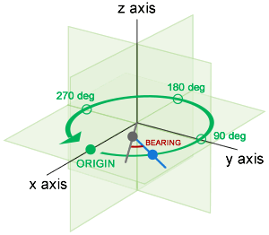
Above: Helm maneuver example. Grey is the previous position/heading, blue is the new heading/position.

To achieve heading changes, the output of the main engines is magnetically gimballed, applying thrust at an angle to the current direction of travel (vectored thrust). This causes the vessel to change direction. This is an extremely efficient way of altering heading given the vessel’s mass and momentum, although velocity must be carefully managed to avoid stress on the vessel's spaceframe.

A heading change is defined by the desired change in direction of travel (the bearing) and the vessel's current speed. The system estimates the impact of the chosen bearing on the vessel's heading and maneuver stresses (see below), before the maneuver is engaged by the helm.

More on Helm Operation

Cruise Mode

Heading changes require vectored thrust. When in cruise mode the engines do not output thrust, so a heading change will automatically cause the engines to apply thrust for as long as required to execute the heading change before powering down again.

For this reason the engines remain running in standby mode even when the vessel cruising. While no thrust is applied during cruise mode, plasma generation continues and magnetic impulse accelerators remain active at minimal power to minimise lag when a heading change is required.

EM Output

Engine output is the most significant source of EM emissions for the vessel, which are detectable by other vessels using EMDAR or other sensor systems.

MIE propulsion outputs EM mainly in IR and magnetic bands. EM output increases with thrust. At upper levels of thrust the interaction of exhaust plasma with magnetic impulse accelerators causes a spike in emitted EM, a phenomenon known as impulse cavitation.
Impulse Operations

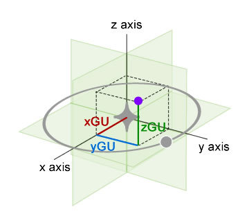
Above: Position (puple dot) is described as coordinates based on distance from the NAO along the X, Y & Z axes 

Impulse operations occur at subluminal speeds (below the speed of light). This navigation mode is used for travel within star systems, where the bulk of Endeavour’s exploratory and tactical operations will take place.

Impulse Navigation

For navigation purposes an arbitrary impulse grid is projected around a star system, centered on the system’s principal astronomical object (usually a star) which is referred to the Navigable Astronomical Object (NAO).

The vessel’s position on the impulse grid is calculated once every second. 

Position

The grid is based on distance from the NAO across X, Y and Z axes represented as Grid Units (GUs), with a distance of 3,000 kilometres between each GU. The vessel’s position is reported as the number of GUs on each axis, in the form of X, Y and Z co-ordinates.

Heading 

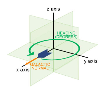
Above: The grid's X axis is aligned to galactic normal, with heading the number of degrees variance from this

The vessel’s direction of travel is its heading. This is represented as the number of degrees variance from Galactic Normal - the calculated centre of the galaxy (similar to the way Earth’s magnetic poles are used as a reference).

The vessel’s direction is changed by altering the direction of engine thrust.

A change in heading is a bearing, measured in degrees from the current heading. 

Course

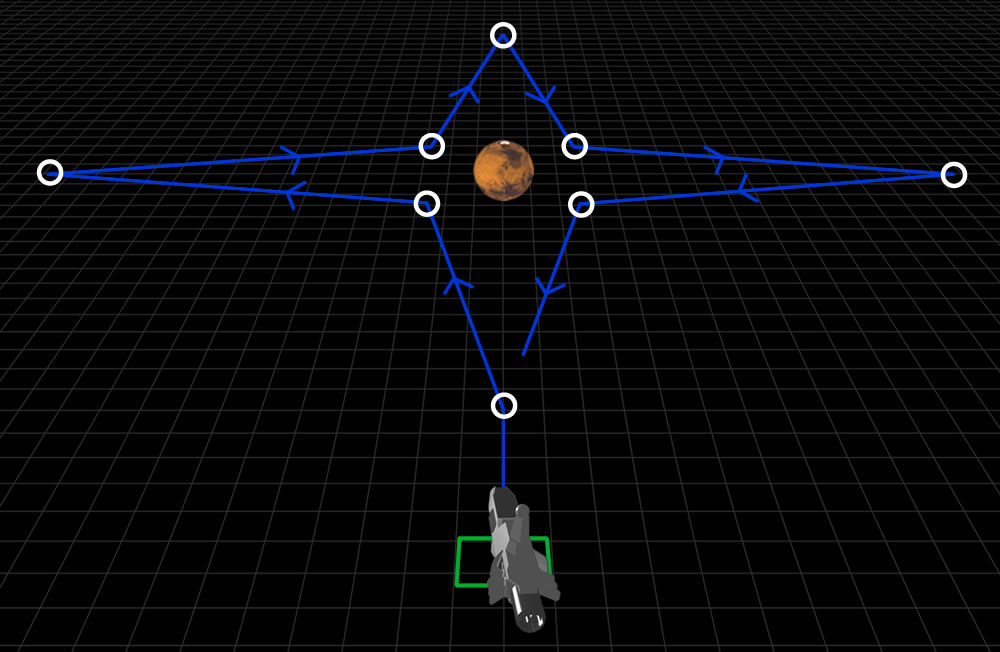
A navigational course is a series of points in space, each represented by impulse grid co-ordinates (a course point), that the vessel aims to reach before applying the necessary bearing to head towards the next point. 

A course may be as simple as a single point where the vessel will stop or enter orbit, or can include serval points, such as a search pattern.

Above: Example of a pre-plotted course (from the 'Martian Star' training exercise). Course points are white.

Courses can be pre-plotted by a navigator and overlaid on the vessel’s current position, such as a complex search pattern, or they can be plotted on the fly by ‘drawing’ them on the helm console.

More on Impulse Navigation

Impulse Maneuvering

Impulse maneuvering involves changing the vessel’s heading and/or speed to follow a course, or for a specific navigational or tactical purpose such as avoiding a hazard or to allow weapons to be fired.

The helm console provides controls to alter speed and heading and provides tools to help calculate the bearings required to reach course points.

Speed

The vessel’s impulse speed is measured as a proportion of light speed (C). Due to the effects of relativistic drag Endeavour’s top speed is estimated at 0.2C (one fifth the speed of light).

The main engines provide thrust to bring the vessel up to its desired speed, after which the engines are powered down and momentum maintains the vessel’s speed.

Slowing or stopping the vessel requires the application of reverse thrust.

Maneuvering Cycle 

As the helm console updates the vessel’s current position once every second, the effect of any changes made on the helm console will not become apparent until the next position update. For this reason the period between position updates is referred to as a maneuvering cycle.

More on Impulse Maneuvering

Orientation

The position of another object relative to the vessel is its orientation.

Orientation is expressed in a few ways depending on the precision required.

The most precise is to expressed orientation as a bearing - the variance in degrees of the object’s position relative to the vessel’s heading.

Less precise but easier to communicate quickly is to using standard naval terminology to describe the object's position relative to the vessel’s heading. 

Navigation Tech

Image

Navigation involves management of the vessel’s movement in space, including superluminal travel between stellar systems and maneuvering the vessel around other vessels and objects at subluminal speeds.

All navigation requires knowledge of the vessel’s current location, speed and heading as well as the location and bearing of any vessels or objects in surrounding space. Movement over any distance necessitates establishing a heading that will get the vessel to the intended destination.

Navigation Modes

There are three main navigation modes.

FTL (Superluminal)

Faster-Than-Light (FTL) navigation involves relativistic superluminal travel, enabling transit between star systems within hours or days. The vessel’s FTL Drive utilises powerful fields which warp space-time, significantly reducing the effective distance the vessel needs to travel between two points.

Travelling in manipulated space-time takes the vessel out of phase with surrounding space. This means the vessel is undetectable but also means that sensor readings or communication outside the drive field are not possible.

More on FTL Navigation

Impulse

The vessel’s main engines provide thrust using magnetoplasma impulse technology. This uses superheated plasma to create a base level of thrust, which is accelerated using magnetic fields arranged in a carefully configured impulse pattern. Referred to colloquially as impulse engines, they can accelerate the vessel to 0.2c – one-fifth of the speed of light.

The impulse engines are also capable of varying the direction of thrust so as to alter the vessel’s heading. This process of turning the vessel while underway is referred to as maneuvering. This makes the powerful thrust of the impulse engines available to alter the heading of the vessel’s considerable mass relatively quickly and efficiently but also requires the vessel to be under way.

Impulse navigation is where encounters with other vessels are most likely and most tactical operations will occur.

More on Impulse Navigation

Reaction Control (RCS)

The Reaction Control System (RCS) uses a number of small chemical rocket engines located around the vessel to make small and precise position or heading changes. RCS is used for establishing orbit, rendezvousing with another vessel or for docking.

RCS can alter the vessel’s position from stationary, but is not powerful enough to maneuver the vessel at impulse speeds.

Stellar Cartography

Stellar cartography involves the identification of star systems and the mapping of their location so that vessels can navigate to them.

This includes the identification of Astronomical Objects (AOs) such as planets within the star system so that vessels can safely navigate within the star system once they reach it.

More on Stellar Cartography

FTL Drive

Image

The FTL (Faster Than Light) Drive is a piece of recovered extra-terrestrial technology that emits intensive gravimetric fields capable of manipulating space-time.

The effect is to propel the vessel at relativistic velocities far in excess of the speed of light (C), even though the vessel's actual velocity does not exceed impulse speeds (up to 0.2C).

Simulations indicate that star systems within 100 light years of the solar system can be reached within days.

Theory

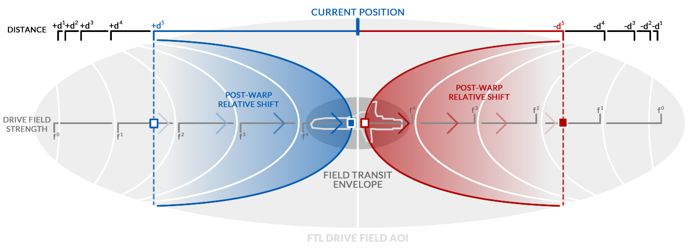
The FTL Drive generates a powerful gravimetric field which warps space-time. Forward of the vessel this effectively brings points in space along the vessel's heading closer to the vessel. This is offset aft of the vessel where the field warps space away from the vessel. This offset means that the FTL Drive field is not compressing space-time overall.

The FTL Drive field extends approximately 100GUs forward and aft of the vessel and only space-time within the field is manipulated. The vessel is isolated from the gravimetric effects of the field by the Field Transit Envelope (FTE), an area at the core of the field only slightly larger than the vessel which is not subject to space-time manipulation and so is effectively 'normal' space.

Overview of FTL drive theory
Above: Overview of FTL drive operation. At the drive field's strongest point, the position marked in blue is shifted relatively closer to the vessel by the field's space-time warping effect. At the same time, a corresponding warp effect away from the aft of the vessel balances this shift, ensuring space-time is not actually compressed overall.

The drive's relativistic velocity is applied to the vessel at the drive field's strongest point (shown in blue/red on the diagram), after which the field's strength drops off exponentially with a corresponding reduction in space-time warping. This gradual reduction avoids gravimetric vortices forming at the leading edge of the drive field.

It is vital that space-time compression forward and decompression aft are precisely matched to avoid any overall compression or decompression of space-time. Any imbalance would generate significant (and potentially catastrophic) gravimetric instability in surrounding space which the FTE may not protect the vessel from.

Engineering

FTL Drive technology has not yet been successfully reverse engineered from the captured device, although a drive device of alien manufacture (recovered from a crashed vessel) has successfully been tested using field emitters manufactured terrestrially.

It is intended that the recovered FTL Drive unit will be integrated into Endeavour, allowing interstellar travel. Eventually it is hoped that the technology can be sufficiently understood to allow the manufacture of new FTL Drive units.

As impulse propulsion cannot be used while the FTL Drive is engaged, the two systems share a common power source, with power shifting between the systems as FTL Drive is engaged and disengaged.

Significant compute resource is required to monitor and continually calibrate FTL drive output to ensure it remains balanced. If the field becomes imbalanced beyond the system's ability to compensate, the drive will be disengaged.

Operation

The FTL Drive itself imparts little or no additional velocity to the vessel. The space-time manipulation effect works off the vessel's momentum at the point the drive is engaged, effectively multiplying the vessel's base inertial velocity.

The FTL Drive requires a minimum base velocity to be effective, estimated to be 0.12C. Higher base velocities induce less load on the FTL drive, which then requires less power to operate.

The amount of power applied to the FTL drive (and therefore the strength of the FTL Drive field) is controllable from the helm.

The helm will prevent the FTL Drive from being engaged if the base inertial velocity is not sufficient for the current drive power level.

While FTL drive is engaged, impulse flight functions are disabled.

FTL Drive Module Operation

Environmental and Tactical Impact

When the FTL drive is engaged it takes a number of seconds for the drive field to form. During this time the FTL drive emits a significant amount of EM in the ionising band (which is detectable but not hazardous).

Once the drive field has formed external observers would notice the vessel visibly distorting before apparently disappearing from view. A similar effect would be noticed when the vessel exits FTL drive mode.

When in FTL drive mode, the vessel is effectively undetectable. This also means that normal communications outside the AOI are impossible, although notifications can be sent and received via the Quantum-Entanglement Relay (QER) system.

Area of Influence (AOI)

The FTL drive field's active Area of Influence (AOI) extends up to 100 GUs (300,000km) forward and aft of the vessel.

External Impact

The effect of objects coming into contact with the AOI from outside is relative to the object's mass and the strength of the drive field. Smaller objects would be deflected by the drive field with minimal impact on the vessel. Objects with sufficient mass would cause the field to deflect away from the object. As this would seriously disrupt navigation and drive operation, the AOI is constantly scanned for unexpected objects of significant mass. On detection the FTL Drive is automatically deactivated to avoid impact, as the navigational changes needed for evasion are too complex given the time available.

It is not thought possible for an object outside the AOI to enter the AOI.

Internal Impact

Any object caught within the AOI (such as when the drive field forms) would be subject to significant gravimetric forces. Objects smaller than the vessel would likely be propelled towards the vessel at superluminal velocities, which could cause catastrophic damage to the vessel. (If the object was aft, it would be propelled away from the vessel).

An object significantly larger than the vessel (such as AOs) would cause the vessel to be propelled towards that object at superluminal velocities, which would result in catastrophic impact (particularly for the vessel).

For this reason FTL drive must not be engaged while objects are within range of the drive's AOI.

FTL Navigation

Standard impulse navigation techniques are not possible while in FTL drive mode as the vast distances involved mean that the slightest error in navigation would be catastrophically magnified.

Instead, FTL navigation is completely managed by computer. The destination system is entered into the helm and the necessary maneuvers to safely reach the destination are calculated, implemented, checked and corrected automatically during flight.

More on FTL Navigation

MIE Impulse Engines

Image

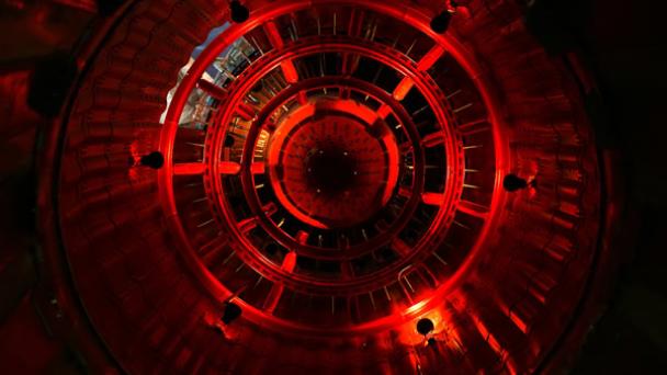
The vessel's main propulsion is provided by Magnetoplasma Impulse Engines (MIE's), which utilise terrestrially-developed magnetoplasma technology combined with an alien-derived magneto-impulse acceleration system.

Operation

MIE engines generate plasma which is directed through a series of powerful magnetic containment fields. The plasma is maintained under pressure to increase its energy level. To generate thrust, plasma is released via a contricted opening in the containment field, with the plasma's energy converted to thrust as it exits at high speed. Escaping plasma is further accelerated by carefuly sequenced magnetic fields generated with in the output nozzle inner surafce. This significantly increases the thrust produced by the plasma to levels necessary for maneuvering a large vessel and to engage superluminal drive systems.

Operating Stages

MIE engines have three operational stages:

Plasma Generation

Fuel gas (hydrogen) is ionized using helicon RF antennas. This creates a relatively dense, cold plasma (60,000K) The resulting plasma is containable by a magnetic field, a requirement for managing the extreme temperatures generated by the next stage.

Plasma Excitement

The initial plasma is fed into a magnetic field designed as a mirror, to trap the low energy initial plasma so that it can be superheated (excited). Plasma is excited using an ion cyclotron resonance heating (ICRH) process, which increases the kinetic energy of the energy of the plasma to the point  that it's controlled escape from containment generates an opposing force - thrust. 

The magnetic containment field is configured to produce a gradeient along the length of the containment chamber, steadily increasing pressure on the plasma to ensure that continued progress through the chamber requires higher energy. The end of the containment field is constricted to ensure that only plasma with high enough energy is capable of escaping. The constriction is periodically lowered temporarily as part of a regular cycle to allow a rush of plasma to escape at high velocity.

Plasma Acceleration

The excited plasma is directed to a magnetic field with an open-ended gradient that creates a magnetic 'output nozzle' lined with powerful magnetic field generators. These generators create a series of constantly variable magnetic gradients arranged to create an impulse pattern that accelerates the plasma and significantly increases the kinetic energy available for conversion to thrust. At a point along the nozzle's magnetic field the field strength becomes weaker than the strength of the plasma's flow and the plasma detaches. it is at this point that thrust is generated.

Directional Control

As the plasma progresses through the acceleration stage, the magnetic field generators can be adjusted to make slight changes to the direction of the plasma flow out of the engine, enough to allow the vessel to be steered.

Reverse Thrust Diverters

An additional series of magnetic field generators can be used to alter the profile of the plasma acceleration and exhaust stage, diverting plasma towards forward-facing output vents. This allows the engines to apply forward thrust to slow and stop forward movement inertia.

The diversion process reduces the efficiency of the plasma acceleration phase, requiring more energy and/or time to apply the equivalent reverse thrust.

Engine Balancing

The engines produce strong magnetic fields which would seriously interfere with other ships systems and cause adverse interactions with planetary magnetospheres.

To counteract this problem, each engine is made up of a pair of ''thruster units'' (each pod consisting of a complete MIE system), with the magnetic fields of each pod oriented as opposite magnetic dipoles.

Propulsion Systems

Image

The vessel is propelled through space by the main Magnetoplasma Impulse Engines (MIEs) at speeds of up to 20% of light, which is suitable for navigating within star systems.

Interstellar travel is achieved using an alien-sourced FTL drive, which manipulates space around the vessel to reduce the time needed to traverse between two distant points in the galaxy.

Other propulsion systems include the Reaction Control Systems (RCS) used on the vessel for docking, stationkeeping and orbital positioning adjustments, and antigravity drives used on small planetary shuttles.

Magnetoplasma Impulse Engines (MIE)

Main propulsion is provided by Magnetoplasma Impulse Engines (MIE's) which fuse existing terrestrial magentoplasma technology with alien-derived magneto-acceleration processes (known as impulse technology).

The first stage emits plasma created from ionising hydrogen, a technology that is well understood but based on current technology does not produce anywhere near the velocities required for deep space exploration. 

The second stage accelerates the plasma using a complex series of powerful magnetic fields generated using alien-derived field generation technology. This massively increases the thrust produced by the engines, allowing velocities of up to 20% of light speed - high enough that relativistic effects become noticeable.

These velocities are suitable for intra-system maneuvering and to attain the relative velocities required for FTL travel.

More on Impulse Engines

FTL Drive

The FTL (Faster Than Light) drive generates the spatial manipulation fields that allow the vessel to reach relative velocities that are significantly faster than the speed of light.

The vessel itself does not reach absolute speeds any faster than those achieved by the main engines - the appearance of FTL speeds is achieved due to space-time manipulation.

The vessel must reach minimum absolute speeds of approximately 10% the speed of light (30,000km/s) before the spatial manipulation fields become effective.

More on FTL

Reaction Control System

The Reaction Control System (RCS) utilises a number of chemical rocket engines to allow minor adjustments to the vessel's attitude and position for close-range and orbital adjustment maneuvers.

Torpedo System

Image

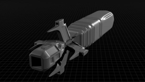
The vessel's primary armament is based around a system of railgun-launched self-guided missiles referred to as torpedoes. 

These torpedoes use the kinetic energy created by their high velocity (tens of thousands of kilometers per second at launch) to penetrate target hulls, where a fused secondary charge ignites remaining guidance-system propellant to create an explosion and shrapnel, damaging the target's vulnerable inner compartments.

Guidance Systems

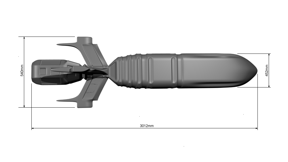
Torpedo side elevation
Above: A torpedo (side elevation). The fins toward the rear stablise the torpedo during launch while the protrusions for each fin house guidance receivers.

Torpedoes are equipped with multiple guidance systems which operate during different flight modes applied at different stages of the torpedo's deployment. These systems are capable of tracking target course changes, allowing the torpedo to change its own heading accordingly using its RCS system.

Targeting Assistance Data Transmission

Torpedoes are provided with target information immediately before launch by the vessel's target acquisition system. The torpedo continues to receive more detailed target information from the vessel than it's onboard guidance system can generate, via a constrained-beam high-frequency link (referred to as a 'wire'). 

The highly targeted nature of this link makes it difficult to jam and intercept, but the need for strict line-of-sight means that any significant course changes by the vessel or torpedo will break the link. Link transmitters mounted near each launcher are capable of dynamically adjusting the direction of transmission to compensate for course changes made by the torpedo.

Independent Passive Guidance

guidance systems which use a small EMDAR array to scan selected EM profiles useful for tracking targets.

Active Guidance

Torpedoes also include a basic RADAR system, which is typically not used until late in deployment to reduce the target profile presented by the torpedo to countermeasure systems.

This link is also capable of transmitting control data, including a change of target.

Reaction Control System

Torpedoes are equipped with a small Reaction Control System (RCS) used to make course changes requested by the guidance system.

The RCS is made up of a small chemical rocket engine with directional control provided by a servo-controlled output nozzle.

The torpedo's main velocity is momentum-based (with the initial momentum provided by the railgun launcher and the launch vessel's velocity). 

Ordnance Configuration Options

Torpedoes use standardised flight casings into which a number of configurable ordnance and sensor options can be fitted, which allows the torpedo launch system to also deploy remote scientific probes.

Warhead Options

Different warheads can be fitted to torpedoes to suit tactical requirements.

Standard Armour-Piercing Configuration

The standard torpedo configuration consists of an armor-piercing casehead and a fused secondary explosive charge designed to ignite remaining RCS propellant and convert the torpedo case into shrapnel to damage interior compartments once the target hull has been penetrated.

Interchangeable Mission Packs

Different sensor packs can be fitted to torpedoes to suit tactical or other operations requirements.

Tactical Sensory Packs

The standard tactical sensory pack passively scans for target EM, heat and exhaust plasma emissions and can also actively scan using RADAR.

Operations Sensory Packs

A number of sensory packs can be fitted to convert torpedoes into probes. The standard sensor-pack compartment in the torpedo case is augmented by the addition of another compartment fitted in place of the warhead, to make room for extra sensory and processing equipment.

Targeting

Configuring a torpedo for successful target prosecution requires the development of a firing solution, which takes account of the range and speed of launch and the torpedo's different flight modes.

More on firing solutions

EMDAR Contact Management

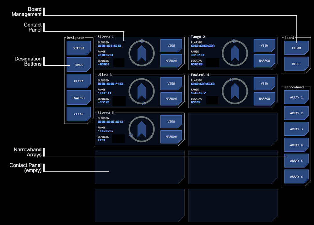
The EMDAR Contact Board module allows management of EMDAR contacts. A contact is an untracked EM emissions pattern thought to indicate a Tactically Significant Maneuvering Object (TSMO). As the EMDAR system is not directional and becomes less accurate over distance operators will typically spend some time managing contacts before accurate enough information can be obtained to achieve tracking with a narrowband array.

More on EMDAR

Process Overview

A contact represents the estimated position of a possible TSMO based on an indicative EM emissions patterns on the Waterfall Displays. By selecting the range to the patterns (on one lateral array and one longitudinal array) the range and bearing to this point in space is calculated.

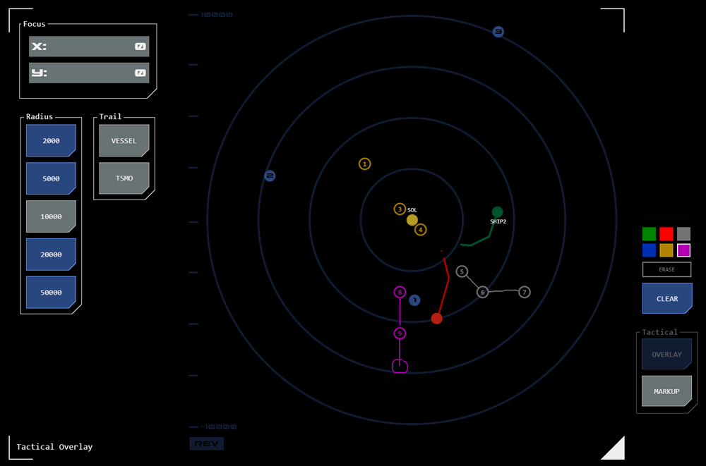
Tactical overlay example
Above: Tactical overlay showing multiple contacts (tracked contacts are green, your own vessel is red). Note the markup that has been added to highlight patterns formed by groups of contacts

It is unlikely that the TSMO's position will be estimated accurately enough on the first contact for tracking purposes. Multiple contacts will likely need to be created for each target as EM patterns are detected (where a target TSMO maneuvers, for example, thereby temporarily increasing its EM output) to refine its location. To help match contacts with their target, each suspected target is given a tag and each contact associated with that target is also assigned that tag.

On the tactical overlay, each tag has its own color:

Sierra: Silver (grey)

Bravo: Blue

Victor: Violet

Tango: Tan (gold/yellow)

This is particularly useful when multiple TSMO targets are suspected.

The contact board provides data on the range and bearing of each contact at the time it was added. Until acquired by a narrowband array a contact cannot be tracked. A contact’s estimated location is defined as a particular point in space and the contact board will update the range and bearing to that point based on movement of the vessel, but not on any shift in location of the contact itself.

A contact’s details can be updated at any time, where the contacts position has been refined, where its tag needs to be changed or if the contact is no longer relevant and can be re-used. Each contact has a time indicating the time elapsed since it was added or last updated.

Once a contact’s EM emissions are strong enough to make tracking possible, the most accurate contact is assigned to a narrowband array. These are a more focussed and directional version of the passive arrays used by the EMDAR system, that can track the movement of an EM source once acquired.

Contact Board

EMDAR contact board overview
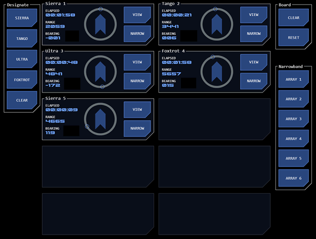
Above: EMDAR contact board example (click for larger)

The contact board can display up to ten contacts. This limit is imposed by the computation resources required to manage the relative position of the vessel and contacts.

Operation/Display Modes

The EMDAR Contact Board has two operating modes.

Monitor Mode

This mode displays contacts currently being managed by the EMDAR team without any associated designation or assignment controls. The commanding officer will likely have a contact board in this mode displayed on one of their command consoles, for example.

Operation Mode

This mode allows contacts to be added to the board, updated and assigned to narrowband arrays. In this mode, the contact board works in conjunction with other EMDAR modules including waterfall displays and the EMDAR monitor. An EM pattern is targeted on the waterfall displays, assessed on the EMDAR Monitor and then added to the contact board.

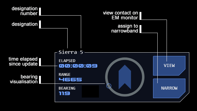
Contact Monitor

EMDAR contact overview
Above: EMDAR contact example (click for larger)

Each contact is displayed underneath it’s designation, which includes a system-assigned contact number. This number is the primary means of identifying a contact, as the tag may change at any time. The number is unique to the current mission phase and is not re-used (until the contact board is reset – see below).

Each contact displays the relative range and bearing to the source EM’s location in space at the time of the contact’s creation or update. The range in bearing is updated to reflect movement of the vessel but not the movement of the source EM pattern (as there is nothing for the system to track). 

A timer indicates how long it has been since a contact was added or updated. The timer will change colour to alert and then alarm status after a predefined time to prompt the operator to update the contact.

Operating Procedures

Adding a Contact

Using the EMDAR waterfall displays, select ranges on one of the longitudinal arrays and one of the lateral arrays (this selection will usually be based on the location of EM patterns of interest).

Selecting these ranges will update the EMDAR monitor with a bearing and directional range and will display the EM profile for that location.

  1. Select the tag for the contact. If this is the first contact, choose sierra (simple) as this is typically the tag used if a particular target isn't in mind. For subsequent contacts that are thought to represent the same target, choose a tag for that target and assign it to all contacts thought to relate to that target. If a new target is suspected, choose a different tag.
  2. On the contacts board, tap an empty contact slot. The contact will be added to the board and the elapsed timer will start.

Updating a Contact

Updating a contact is required when its tag changes or where it is preferable to refine the contact's location rather than create a new contact (where the contact is about to be assigned to a narrowband array, for example).

  1. Within the contact that is to be updated, click the VIEW button. This will:
    1. Transfer the contact’s location to the EMDAR Monitor which will change colour to indicate it is displaying details from a contact.
    2. Change the bearing indicator for that contact to a matching colour to indicate the link with the EMDAR Monitor.
    3. Display the contact’s current settings in the Designate button group.
  2. To change the tag:
    1. Select the new tag in the Designate button group.
    2. Click UPDATE in the contact. The button will indicate the update has been completed.
  3. To update the location of the source EM pattern:
    1. Click the EM pattern’s new location on the lateral and longitudinal array.
    2. The EMDAR Monitor and EM Profile will update to reflect the new location
    3. Click UPDATE on the contact. The button will indicate the update has been completed.
  4. Steps 2 and 3 can be performed separately or as part of the same procedure.

Deleting a Contact

Contacts can be removed from the board when it is no longer necessary to manage a contact (because the source EM pattern has disappeared from the waterfall display, for example).

  1. Click VIEW on the contact that is to be removed
  2. Click CLEAR at the bottom of the Designate button group.
  3. Click UPDATE on the contact.
  4. Confirm the deletion. The contact will be removed from the group.

The deleted contact’s designation number will not be re-used unless the board is reset, to avoid confusion.

Clearing or Resetting the Board

All contacts can be removed from the board at once with the Board button group.

  1. To remove all contacts without resetting contact numbers:
    1. Click the CLEAR button.
    2. Confirm the clearance. All contacts will be removed. Contact numbers will not be reallocated.
  2. To remove all contacts and reset contact numbers:
    1. Click the RESET button.
    2. Confirm the reset. All contacts will be removed and contact numbers will be reallocated starting from 1.

Allocating a Contact to a Narrowband Array

Where a contact’s location is considered accurate enough it becomes possible to direct a narrowband array to acquire and track the contact source.

  1. Click NARROW on the contact that is to be allocated. The button will indicate that the contact is to be assigned.
  2. Select an unassigned narrowband array from the Narrow button group. The selected button will change to indicate the array is in use.
  3. The circular bearing indicator in the contact will change colour to indicate that the contact is being tracked by a narrowband array.
  4. If the acquisition process fails, an error state will be indicated and the contact and array button will reset to their normal states.

If a contact is tracked it will remain on the contact board, but its range and bearing will be updated automatically as long as it remains tracked.

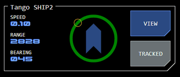
Tracked Contact Display

EMDAR tracked contact exampleA tracked contact (or "track") is identified by a green bearing track and the display of the TRACKED button with active status.

The contact's designation number is replaced by a unique code.

The elapsed time is replaced by an estimate of the TSMO's speed.

Tracked Contacts and Designation

All tracks appear as green on the tactical overlay and are labelled with the contact's number. As such, tracks do not use tag colours - they are assigned a designation instead. The designation indicates the target's tactical posture:

Sierra: Unkown posture

Bravo: Friendly posture

Tango: Threat posture

Victor: Neutral posture

When created a track retains the equivalent designation the contact was tagged with, but this should be changed to the appropriate designation.

To release the designation from a track, use the same procedure as if you were deleting a contact (see above). The first time you do this with a contact, it will remove the designation. If you use the deletion procedure again on a track that does not have a designation, the track will be deleted.

It is possible to add a designation back to a track (or change an existing designation) using the same procedure as for contacts.

Releasing or Losing a Track

A track may be released manually by tapping the contact's TRACKED button. A confirmation dialog will ask for confirmation of the release.

A track is lost if the TSMO goes out of EMDAR range or where an AO comes between the vessel and the TSMO.

If a release or loss occurs, the track will revert to a contact. The contact's position will be updated with the last tracked position of the TSMO.

Narrowband EMDAR

Narrowband EMDAR uses the same passive EM detection system as broadband EMDAR but is far more directional, focusing on a very limited area of space.

The narrow focus limits the amount of detection data that needs to be processed, which means a narrowband array can calculate movement and adjust its focus accordingly, allowing it to track a moving EM source such as a TSMO.

In addition to EM detection the narrowband system utilises computational analysis which can extrapolate not just position but also the TSMO's speed. An extrapolation of the TSMO's EM emissions at source is also available, allowing assessment and comparison of a TSMO's EM 'signature'.

Achieving a Track

The successful detection of a TSMO by a narrowband array is referred to as a ‘track’.

Before a narrowband array can begin tracking a TSMO, it’s narrow area of focus means that it must be directed to the area of space within +/-100GU’s of the TSMO’s location. The contact management process allows operators to continually refine their estimate of a TSMO’s location using the broadband EMDAR system until a narrowband array can achieve a track.

Contact Management

Maintaining a Track

With their combination of directional EM detection and enhanced analysis, narrowband arrays can track EM sources which might not otherwise attract attention on a waterfall display.

Narrowband EMDAR is still subject to AO masking effects. For example, if an AO such as a planet comes between the tracking ship and TSMO, the track will be lost.

Equipment Limitations

Narrowband arrays are positioned around the vessel in redundant, overlapping sets. The directional nature of narrowband requires line-of-sight (LOS) to the target. An array will automatically hand off tracking to another when a target moves out of LOS.

While there are a significant number of physical narrowband arrays installed, the need to keep arrays spare at each location for tracking handoff and the significant computational resources required by the system means that only six virtual arrays are presented to operators for use. This limits the maximum number of tracks that can be maintained, but is thought to be adequate for most tactical scenarios.

EMDAR

Image

Electromagnetic Direction and Ranging (EMDAR) is a passive sensor technology that detects emissions along the EM spectrum to identify and track other vessels. The system is passive because it does not emit any EM to make its detection (in the way that RADAR does with radio waves). Instead, the system detects EM radiation falling onto its sensors and calculates likely distance using dispersal patterns, a process very similar to SONAR.

The advantage of the passive system is that it does not provide any EM emission for an opposing vessel to detect. The disadvantage is that passive systems can only achieve relatively weak readings, sometimes difficult to distinguish from background radiation. Dispersal patterns also become increasingly less predictable over distance, making range estimations less certain. 

Broadband EMDAR

EMDAR uses broadband detection techniques which estimate the range of an emission source by analysing EM dissipation patterns, but are less useful for identifying bearings (direction). As such, a single EMDAR array cannot estimate the speed or course of an object.

Multiple EMDAR arrays with different directional orientations are used to provide additional data for estimating speed and course. The vessel has a forward-facing array and a pair of lateral arrays (port and starboard). Exhaust from the impulse engines prevents the use of an aft array, but a remote array can be launched to provide EMDAR coverage astern.

By comparing the behaviour of an object across multiple EMDAR arrays, conclusions can be drawn on and object’s course and speed.

Waterfall Interface

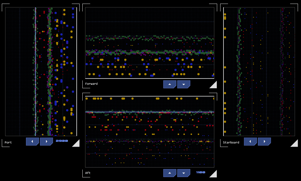
Each EMDAR array presents detection data as a grid defined by range and time axes. A detection is represented as a dot, its position indicating estimated range and the time since detection. The colour of the dot represents the EM range of the detected emission and the dot’s size represents the intensity of the emission.

EMDAR waterfall display example
Above: Example of an EMDAR interface (click for larger). Detected emissions first appear on left or top with time elapsing to the right or downwards (depending on orientation of the array display).

Presenting historical detection data allows patterns to form, typically as a line (or trail) across the display (hence the name waterfall for these types of visualisations). These patterns can provide hints as to course and speed.

Example

By way of example, sample EMDAR displays are shown in the picture to the right.

This example is simplified in that it shows only static contacts and the vessel itself is not moving. Were either in motion, the waterfall trails would appear to "drift" in the direction of travel. For example, if a contact was getting closer to the vessel, the top (or left side) of the trail representing the most recent detections would have a closer range than the lower (or right) end of the trail which contains less recent detections. When trail drifts are considered across multiple arrays, an experienced EMDAR operator is able to discern a great deal about a TSMO's relative course and maneuvering.

Contacts

EMDAR contact board example
Above: EMDAR contact board example (click for larger).

The crew monitoring EMDAR can declare a contact if they believe a detection represents the location of a TSMO, passing the coordinates to the Contact Board.  The tactical officer will generally alert the conn to the contact's creation along with whatever additional information they can provide such as heading, range, maneuvering patterns, etc.

It is likely that multiple contacts will be generated by the same TSMO over time. Once multiple contacts are on the board, it may be easier to infer the TSMO's course, helping to focus the search. To facilitate this, each TSMO is given a designation, so that contacts associated with it are easily identified. Where the crew suspects they are monitoring multiple TSMOs, each is given a different designation.

Contact Management

Transition to Narrowband

A designated contact will appear on the Contact Board and the system will automatically track the identified location in space relative to the vessel's own movement. At this stage the system does not have sufficient information to track the object that is emitting the EM, so each contact represents a fixed point in space.

In order to automatically track the location of a TSMO, a narrowband EMDAR array must be used. As narrowband EMDAR can only analyse a small area of space, it must be directed toward the TSMO's location in order to achieve a track.

Once broadband EMDAR has estimated the TSMO's location with sufficient accuracy, a contact may be assigned to a narrowband array for tracking.

Once a contact is tracked, any other contacts with the same designation used as part of the tracking process are cleared. The track's designation is now used to identify its target profile, such as "friendly" (bravo), "threat" (tango) or "neutral" (victor), leaving sierra for contacts with unknown posture.

Narrowband EMDAR