


Related
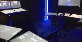
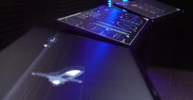
The Vessel Command, Control and Management System (VC2MS) is intended to facilitate intuitive access to relevant system information for rapid diagnosis and control input.
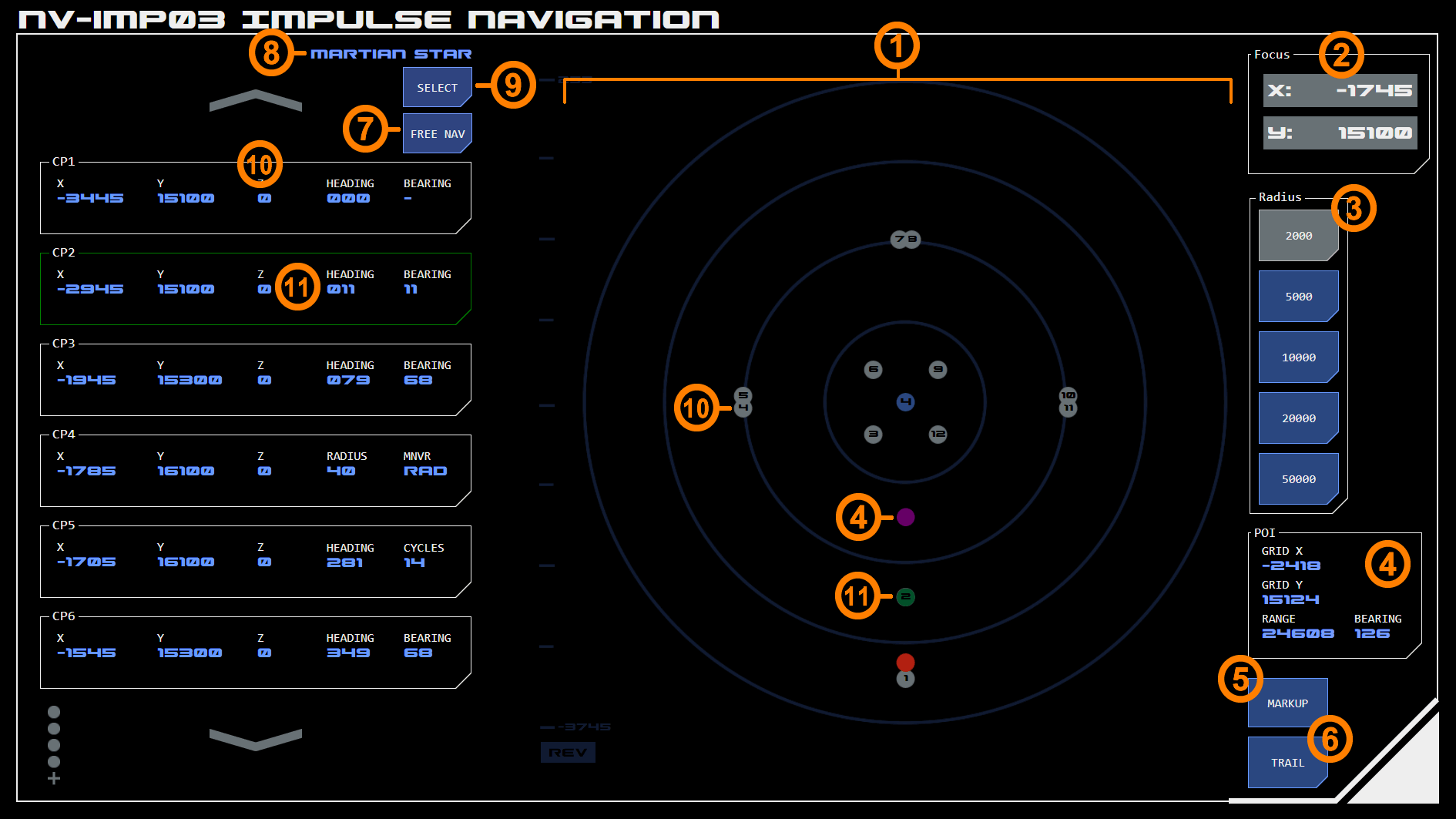
The Impulse Navigation panel assists with navigation against pre-plotted courses during impulse operations.
The panel consists of a scrollable list of course points and a 2D impulse map displaying the location of the course points, Astronomical Objects (AOs) and the vessel.
The console has two modes.
Pre-plot mode allows the user to select from a list of courses plotted by a navigator, typically standard search patterns or a course with specific mission requirements.
Free-nav mode allows the user to select Points of Interest (POI's) from the impulse map and save these as course points.
Common Features
The console has a number of features which are common to both modes.
1. Impulse Map
The impulse map displays course points as silver dots, with the point’s order number displayed in the centre. The currently highlighted course point is displayed as a green dot.
Where multiple course points overlap, the earliest course point will be displayed until the vessel navigates beyond the following course point, after which the later course point will be displayed.
Stars are displayed as yellow dots with their designation listed below. Other AO’s are displayed as blue dots with their system number displayed in the centre.
Other impulse map features such as the ability to set the map’s focus co-ordinates and radius (scale) work as normal. Focus and radius may be updated automatically when a new course is selected, although this can then be overridden by the user.
Markup and course trail options can be activated at the bottom right of the map ((7).
2. Focus
The center of the impulse map is it's focus. The co-ordinates of the map focus can be set here.
Alternatively, tapping the currently active radius button will re-focus the map on the vessel.
3. Map Radius
The impulse map's radius (in GUs) can be selected from one of five options.
Courses Relative to Map
Courses are relative to the panel's current focus and map radius. Changing either will shift all course points to match the change.
4. Point of Interest (POI)
Tapping any point on the impulse map will activate a purple dot (which represents the POI) and display the POI's co-ordinates in an interface at the bottom right of the panel. Bearing and range of the POI from the vessel are also displayed.
5. Markup
This activates the markup capability of the impulse map, which allows users to draw lines on the map representing possible courses, areas of concern, etc. See the impulse mapping module page for more detail on this feature.
6. Navigation Trail
Tapping this toggles between showing a navigation trail behind the vessel, which indicates previous navigation activity.
7. Mode Toggle
This button toggles between pre-plot and free-nav modes (see below).
Pre-Plot Mode
This section refers to the pre-plot example above.
8. Current Course
This indicates which pre-plotted course is currently being displayed (in this example the Martian Star course for training exercises).
9. Course Select
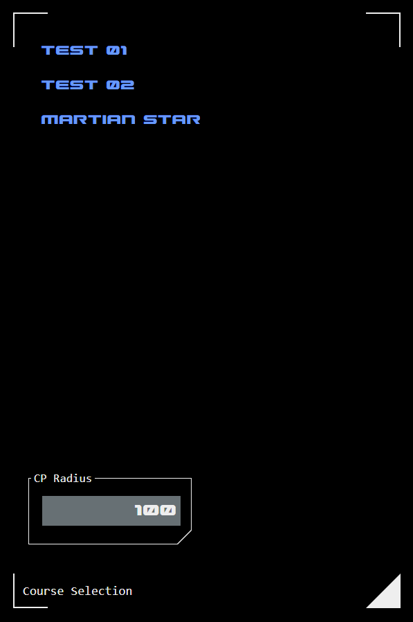
Tap this button to select a new course from a list of available courses.
When a new course is selected it may include default radius and focus information. If so, the impulse map will automatically update with this new configuration.
10. Course Point List
This scrollable list displays the course points included with the selected course. An example course point is shown.
Each course point includes the grid co-ordinates, the heading required from that course point, and the bearing required to achieve that heading. The first course point does not show a bearing as this is dependent on the approach heading.
The displayed bearing is relative to the previous course point and does not update based on the vessel's heading, even when the course point is currently the target (see 11 below).
Maneuver Types
Where appropriate particular maneuver types will be specified for a course point.
Radial Maneuver
A radial maneuver requires a bearing applied over a series of maneuvering cycles that results in a circular course of a particular radius.
A radial maneuver has two course points. The entry course point has a maneuver type of RAD and specifies the radius required for the maneuver (instead of displaying a heading). In the example panel image, CP4 is the entry course point for a radial maneuver.
The exit course point displays the heading required at the end of the maneuver, but displays the number of maneuvering cycles required to reach that heading (instead of displaying a bearing). The number of maneuvering cycles is calculated based on the currently selected cruise speed and the radius specified in the entry course point. The underlying calculation is the same used by the Held Bearing Calculator (HBC). In the example panel image, CP5 is the exit course point for a radial maneuver.
11. Current Target Course Point
The specific course point currently being navigating towards is highlighted green (as is the corresponding dot on the map). On loading the panel the first course point is highlighted by default. The highlight can be moved by tapping the desired course point. To remove the highlight, tap the already highlighted course point.
When the vessel navigates to the current course point the highlight automatically moves to the next course point. The sensitivity of this (ie how close the vessel has to get to the course point to trigger the change) is adjustable using the CP Range dialog under the course selection list.
Free-Nav Mode
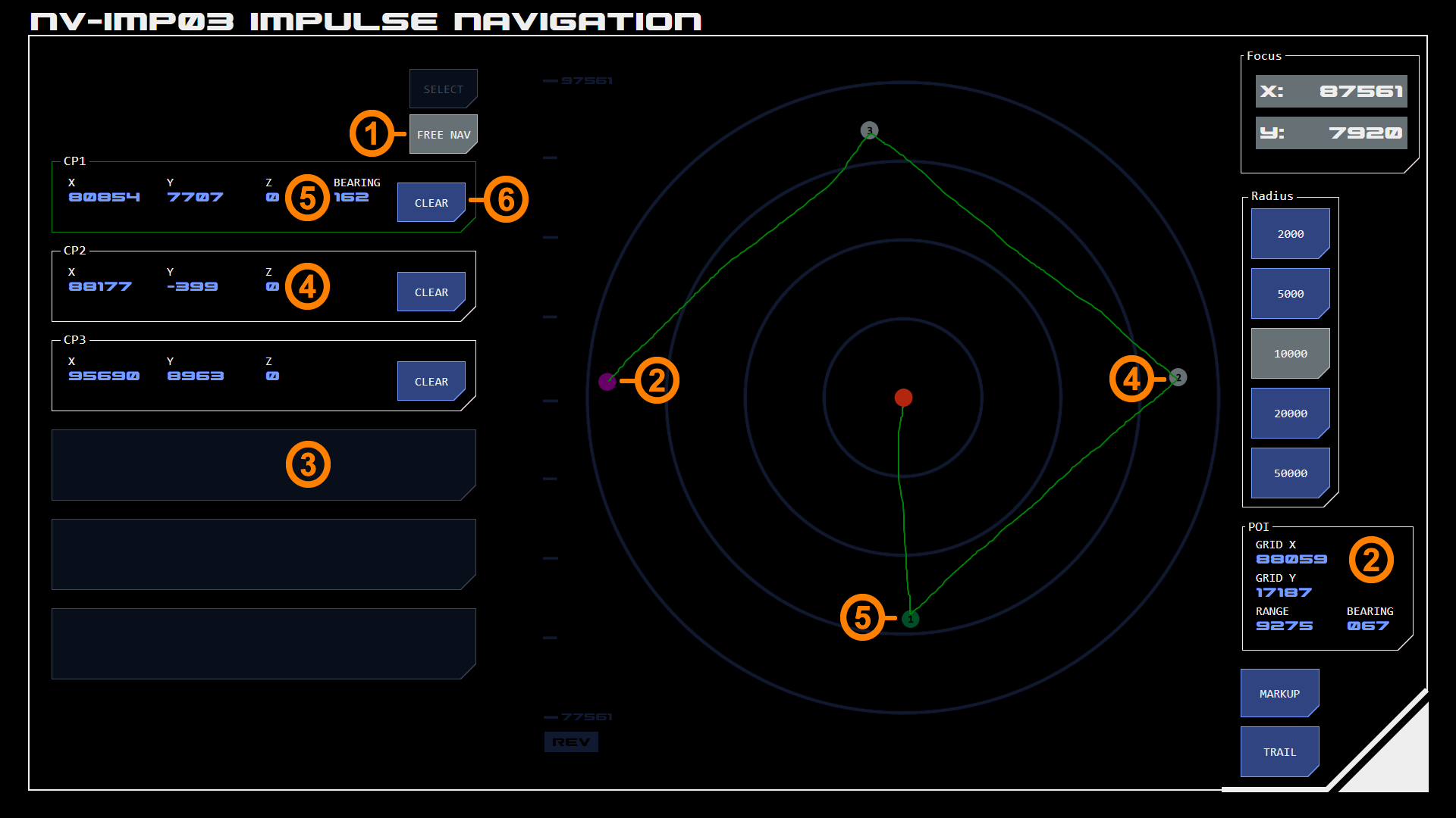
In this mode users can select their own course points on the impulse map. This is usually done in conjunction with markup - a course is drawn on the map (shown in green on the example) and course points selected where heading changes are required by the drawn course.
1. Mode Toggle
When in free-nav mode the mode toggle button displays selected state.
2. Point of Interest (POI)
The POI is displayed the same way in both nodes, but in free-nav mode the purple dot and POI data display indicate what will be transferred to the course point list.
3. Course Point List Target
Any empty course point list item can be selected to add a course point. When tapped, the list item will be populated with the current POI data and a corresponding course-point will replace the POI dot on the impulse map.
4. Course Point
The course point list displays grid co-ordinates for each course point. Course points are shown on the map as silver dots with their course point number in the centre.
A maximum of six course points can be plotted at any one time.
Course points will always have the number corresponding to their position on the list.
5. Target Course Point
The course point currently being navigated toward (the target course point) can be selected by tapping anywhere in the course point item (except the CLEAR button).
This changes the item's border to green (with the corresponding dot on the impulse map also changing to green).
A target course point will also display the current bearing from the vessel to that course point. This is constantly updated.
Unlike pre-plot mode, the target does not automatically change to the next course point. Users can manually select the next course point by tapping it.
Tapping the current target will disengage it as a target.
6. Clear Course Point
Tapping the CLEAR button removes the course point from the course point list and map.