


EMDAR Waterfall Module
 The EMDAR waterfall module presents EMDAR detections on a distinctive visualisation that provides historical context and allows pattern analysis to help identify possible contacts.
As they are directional, multiple modules will be required to provide complete coverage of the vessel. Modules are configurable to reflect their expected orientation.
Layout
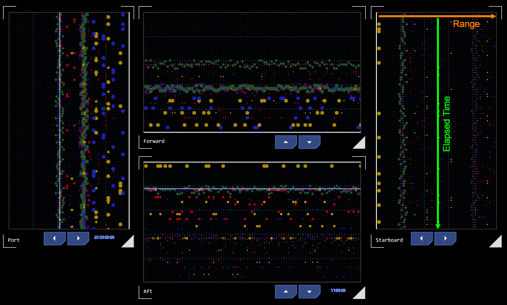
Each module represents an EMDAR array and is laid out differently depending on the array it represents: longitudinal arrays are presented with a horizontal time axis, lateral arrays are presented with a vertical time axis. There are four arrays in a 2D environment: forward, aft, starboard and port. The modules are intended to be displayed as a group with the centre of the group representing the vessel (zero range). Zero range is indicated on the module by a wide border.
Detections
Each module gets the latest detections from the EMDAR detection module that have been assigned to that array. Detections include information about the EM band of the detection, its intensity and its range from the vessel. There may be a number of detections at any one time.
Each detection is presented as a coloured dot. The colour of the dot represents the EM band and the size of the dot represents intensity. Detections are positioned along the range axis according to their range from the vessel.
The module checks for new detections at a regular interval. When a new set of detections is processed, the previous set is pushed down the time axis. Up to 100 sets of previous detections can be displayed along the time axis, displaying patterns which can provide insights into the relative movement of the TSMO that may be generating the EM.
Orientation
Forward and aft are longitudinal arrays. Port and starboard are lateral arrays.
Filtering
Check button modules can be configured to work in conjunction with waterfall modules to allow filtering of EM bands.
Target Selection
If EM patterns at a particular range are of interest for creating a contact, the operator may touch the screen at that point to place a target line. The range of the target line (in grid units) will be displayed. Two directional buttons at the bottom of the module allow the position of the target line to be fine-tuned by moving it one graticule unit in the indicated direction.
Only one of the two arrays in an orientation (longitudinal or lateral) can display a target line at a time. When there is one target line in the longitudinal group and one target line in the lateral group, the convergence of the two lines is displayed on the EM Monitor module. This displays the bearing and range to that convergence point. This information can then be used to create a contact.
Concept Site
Immersive sci-fi and how to join the adventure
Crew Site
Information and tools for ISDC crew members


