


PDN Nodes

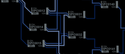
Power distribution nodes are used to route and convert power across the vessel's Power Distribution System (PDN).
Design
Each node can receive power from up to three sources via its upstream interface. The supplied power is aggregated and made available for allocation to up to three other nodes via its downstream interface.
 Power is distributed to and from a node via connected conduits.
Distribution nodes typically have a number of both upstream and downstream conduits to ensure redundant power routing options and for efficient power distribution.
Standards Conversion
A node can convert power standards before distributing to downstream nodes if equipped to do so. This capability is specific to the node's hardware and is not a configurable option.
Supply Nodes
Supply nodes are connected directly to a power generation source such as a reactor or auxiliary power system and so only have a downstream interface (to deliver power).
System Nodes
System nodes are connected directly to a ship system that uses the supplied power and so only have an upstream interface (to receive power).
In addition to the power connection there is also telemetry connectivity between a system node and the ship system being supplied with power. This enables a system node to monitor and report on the status of the connected system via the node's diagnostic interface (see below).
Control Interface
Each node has a control interface which manages the distribution of power from upstream to downstream interfaces and provides system status and diagnostic information.
 The control interface can be launched from a PDN console panel, or from a system panel using the POWER button.
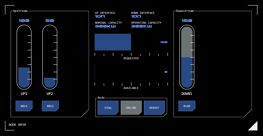
The control interface displays as an overlay and has three main areas:
Upstream Interface
Controls for the upstream interface are on the left (not displayed for supply nodes). A linear slider for each connected upstream conduit will be displayed.
The amount of power being supplied by the upstream node is represented by the slider's grey background. The slider can be used to allocate power from that source to the node.
The maximum capacity of each slider is the same as the node's nominal capacity.
The connected upstream node is identified on a button below the slider. Tapping the button will open that node's control interface (where the control interface is accessed from a PDN console panel - this option is not available where the control interface is accessed from a system panel).
If available power from an upstream node is reduced, the power allocated to the displayed node will be reduced accordingly. When power levels from the upstream node are restored the power allocated to the displayed node do not revert to their original levels. The power allocation must be increased manually.
Downstream Interface
Controls for the downstream interface are on the right (not displayed for system nodes). A linear slider for each connected downstream node is displayed.
The grey background for downstream linear sliders is always at maximum as there are no restrictions on how much of the displayed node's available power can be allocated to any one downstream node.
Power is allocated to a downstream node using its slider. As power is allocated, the available power display (in the central node status section of the control interface) changes accordingly. When all of the node's available power has been allocated, a downstream slider will not increase any further and its numerical display will flash an alarm state.
The connected downstream node is identified on a button below the slider. Tapping the button will open that node's control interface (where the control interface is accessed from a PDN console panel - this option is not available where the control interface is accessed from a system panel).
Conduit Status
The status of conduits connecting downstream nodes is monitored. If there is an issue with the conduit, the colour of the button for the connected downstream node will change to reflect the conduit's status:
Off state: The conduit has been disconnected
Alert State: An issue with the conduit has been detected but delivery of power has not yet been affected
Alarm state: The conduit cannot deliver power
A diagnostic code (see below) will typically be raised if there is an issue with a conduit.
Node Status
The node's status is displayed in the centre of the control interface.
The top of the status area displays data about the node's configuration:
Up Interface: This is the power standard accepted by the node's upstream interface
Down Interface: This is the power standard output by the node's downstream interface
Nominal Capacity: This is the capacity (in KW) that the node is rated to handle
Operating Capacity: This is the current capacity (in KW) that the node can handle. This may change if the node becomes damaged, for example.
Below this data two linear monitors display current power availability:
Requested Power
The requested linear monitor indicates how much power has been requested from upstream sources, as a total across all upstream inputs.
Available Power
The available power linear slider indicates how much power remains available to be allocated to downstream outputs.
As power is allocated to downstream inputs this slider will reduce accordingly until all available power has been allocated.
Node Condition
 Three buttons at the bottom of the node status area provide monitoring and configuration options:
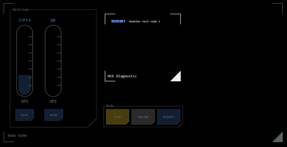
DIAG Button
This button will display the nodes current diagnostic status:
Alert State: The node is operating sub-nominally and capacity may be reduced.
Alarm State: The node is inoperable and cannot distribute power.
Tapping the DIAG button will display an overlay with any applicable diagnostic codes.
Online Button
Tapping this button allows a node to be toggled online or offline.
Selected State: The node is online.
Available State: The node is offline but can be made online
Off State: The node is offline and cannot be made online (usually because the node is inoperable, which would be indicated via the DIAG button).
Reboot Button
This button reboots the node's Power Control Unit (PCU).
Where a node is inoperable or operating subnominally, depending on the diagnostic code it may be possible to clear the condition with a reboot.
Categories:
Concept Site
Immersive sci-fi and how to join the adventure
Crew Site
Information and tools for ISDC crew members


